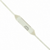
EYP-2BN143 Panasonic - ECG, EYP-2BN143 Datasheet - Page 7

EYP-2BN143
Manufacturer Part Number
EYP-2BN143
Description
THERMAL CUTOFF 145C 2A/250VAC
Manufacturer
Panasonic - ECG
Series
Nr
Datasheet
1.EYP-2BN082.pdf
(7 pages)
Specifications of EYP-2BN143
Holding Temperature @ Voltage
120°C (248°F) @ 250V
Rated Functioning Temperature
293°F (145°C)
Approvals
BEAB, CSA, UL, VDE
Package / Case
Axial
Lead Free Status / RoHS Status
Lead free / RoHS Compliant
Other names
EYP2BN143
P10925
P10925
2. Soldering, Welding, Calking
3. The use of suffi ciently fl exible, appropriate free length and proper size wire should be used for splice connection.
4. Where the lead wires of the TCO is tied with string, put them at least 10 mm apart from the seals of the main
5. Quality control notes.
6. Storage method
7. Do not repair a TCO. Replace it with a new part.
Design and specifi cations are each subject to change without notice. Ask factory for the current technical specifi cations before purchase and/or use.
Should a safety concern arise regarding this product, please be sure to contact us immediately.
Lead Length ( )
1) Lead wires are to be soldered with the standard conditions shown in Table 1.
2) Avoid preheating and gradual cooling as much as possible. However if preheating and gradual cooling is
3) Do not use refl ow soldering.
4) Thin type (MP and MU series) is not to be soldered.
5) If water or solvent is used for cleaning fl ux after soldering, check and confi rm the reliability of the agent.
6) Lead wires are to be clamped at least 3 mm away from the seals.
7) Set the conditions for welding and calking only after checking contact resistance and connection strength.
8) When resoldering or rewelding, cool the TCO under room conditions.
9) When the TCO is heated by soldering or welding, be careful not to pull, push or twist the TCO lead wires.
Connection including connectors used for splicing shall be of the low resistance type, and they shall be made
mechanically secure.
body of the TCO.
1) Measurement of resistance between lead wires (terminals) and checking of the internal status with X-rays are
1) Store the TCO in packing cases or in polyethylene bags within the temperature range -10 °C to +40 °C and
2) Avoid storage in places containing corrosive gases such as sea breeze, Cl
3) The period of guarantee for performance such as solderability is for one year after our delivery; and this
Bending
Excessive soldering heat and soldering time may cause damage to a TCO.
If higher temperature, longer time or shorter lead length exist rather than the conditions of Table 1 ,it is
recommended to run tests for fi nd ing the soldering conditions that do not
tools such as pliers are recommend ed to dissipate the soldering heat by grasping lead wires between the
TCO body and soldering point.
done, set the process conditions after confi rming that the TCO is not affected by these procedures.
Improper connections may cause damage to the seals or other parts and may result in nuisance tripping of
the devices due to the generation of excessive heat at a faulty high resistance junction.
effective means to confi rm the status of the TCO on delivery and after mounting in the equipment.
RH of 30 % to 75 %. Store them at a location where no rapid changes of temperature or humidity or no
direct sunlight is applied. The location must also be free from vibration and shock .
condition applies only in the case where the storage method specifi ed in above has been followed.
30 mm
25 mm
20 mm
15 mm
> 3 mm
N127, N134, N143
N082, N099
N109, N110
> 3 mm
Temperature of Soldering: 300 °C
F115, F134,
F138, F145
F101
> 3 mm
Table-1 Soldering Conditions
grasped
Type No.
– 387 –
Fig-1
E115, E134, E138
Cutting
Time: 3 s
E101
E145
> 3 mm
H115, H134, H138
> 3 mm
H101
H145
2
, H
2
damage the TCO. Also, use of
S, NH
Thermal Cutoffs (TCO)
3
, SO
2
> 3 mm
and NO
● Soldering point
2
00
.
grasped
Sep. 2010


