CDNBS08-PLC03-6 Bourns Inc., CDNBS08-PLC03-6 Datasheet

IC TVS ARRAY 2-LINE 6V 8SOIC

CDNBS08-PLC03-6

Manufacturer Part Number
CDNBS08-PLC03-6
Description
IC TVS ARRAY 2-LINE 6V 8SOIC
Manufacturer
Bourns Inc.
Datasheet

Specifications of CDNBS08-PLC03-6

Package / Case
8-SOIC (3.9mm Width)
Voltage - Reverse Standoff (typ)
6V
Voltage - Breakdown
6.8V
Power (watts)
2000W
Polarization
2 Channel Array - Bidirectional
Mounting Type
Surface Mount
Applications
General Purpose
Number Of Circuits
2
Voltage - Working
6V
Voltage - Clamping
20V
Technology
Diode Array
Polarity
Unidirectional
Channels
2 Channels
Clamping Voltage
20 V
Operating Voltage
6 V
Breakdown Voltage
6.8 V
Termination Style
SMD/SMT
Peak Surge Current
100 A
Peak Pulse Power Dissipation
2000 W
Capacitance
6 pF
Maximum Operating Temperature
+ 150 C
Minimum Operating Temperature
- 55 C
Dimensions
5.6(Max) mm W x 5.6(Max) mm L
Lead Free Status / RoHS Status
Lead free / RoHS Compliant
Lead Free Status / RoHS Status
Lead free / RoHS Compliant, Lead free / RoHS Compliant
Other names
CDNBS08-PLC03-6TR

Available stocks

Company
Part Number
Manufacturer
Quantity
Price
Part Number:
CDNBS08-PLC03-6
Manufacturer:
BOURNS/伯恩斯
Quantity:
20 000
The markets of portable communications, computing and video equipment are
challenging the semiconductor industry to develop increasingly smaller electronic
components.
Bourns offers Steering Diode/Transient Voltage Suppressor Array combination diodes
for surge and ESD protection applications in an 8 lead narrow body SOIC package
size format.
The Bourns® device will meet IEC 61000-4-2 (ESD), IEC 61000-4-4 (EFT) and IEC
61000-4-5 (Surge) requirements.
Notes:
1. Measured between I/O pins and ground (pin 1 or 2).
2. Measured between I/O pins (pins 1 to 4).
3. See Pulse Wave Form. For an 8/20 µs waveform, apply positive pulse to pin 1 to 8 to pin 2 or 3 (ground).
4. Measured between pin 1 or 8 to pin 2 or 3; pin 1 or 8 to pin 4 or 5.
5. See Peak Pulse Power vs. Pulse Time.
*RoHS Directive 2002/95/EC Jan 27 2003 including Annex
Specifications are subject to change without notice.
Customers should verify actual device performance in their specific applications.
Parameter
Junction Temperature Range
Storage Temperature Range
Electrical Characteristics (@ T A = 25 °C Unless Otherwise Noted)
Thermal Characteristics (@ T A = 25 °C Unless Otherwise Noted)
General Information
Parameter
Capacitance @ 0 V 1 MHz
Working Peak Voltage
Min. Breakdown Voltage I @ 1 mA
Max. Clamping Voltage @ 8/20 µs V C @ IPP
Max. Leakage Current @ V
ESD Protection: IEC 61000-4-2
Peak Pulse Power (tp = 8/20 µs)
EFT Protection: IEC61000-4-4 @ 5/50 ns
Surge Protection: IEC61000-4-5 @ 8/20 µs
Surge Protection: Telcordia GR1089
(Intra-Building) @ 2/10 µs
Contact Discharge
Air Discharge
L4 (Line-Gnd)
L4 (Line-Line)
1
2
WM
5
3, 4
CDNBS08-PLC03-6 Steering Diode/TVS Array Combo
Features
Lead free as standard - RoHS compliant*
Telcordia GR1089 (Intra-Building)
Protects 2 lines
ESD protection > 40 KV
Low Capacitance 6 pF
Symbol
C
C
V
V
P
V
j(SD)
j(SD)
WM
I
Symbol
BR
D
PP
F
T
T
STG
J
Min.
±15
100
6.8
±8
40
95
48
Min.
-55
-55
Nom.
Nom.
16
+25
+25
6
8
1
Applications
T1/E1 & T3/E3 line cards
ISDN U-Interface and S/T Interface
xDSL
Ethernet – 10/100 Base T
20.0 V @ 100.0 A
7
2
Max.
+150
+150
Max.
2000
20
25
8
6
6
3
Unit
5
4
°C
°C
Unit
µA
pF
pF
kV
kV
W
A
A
A
A
V
V
V

Related parts for CDNBS08-PLC03-6

CDNBS08-PLC03-6 Summary of contents

Page 1

... Specifications are subject to change without notice. Customers should verify actual device performance in their specific applications. Features ■ Lead free as standard - RoHS compliant* ■ Telcordia GR1089 (Intra-Building) ■ Protects 2 lines ■ ESD protection > Low Capacitance 6 pF ■ CDNBS08-PLC03-6 Steering Diode/TVS Array Combo Symbol Min. C j(SD) C j(SD 6 ...

Page 2

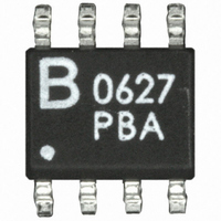
... CDNBS08-PLC03-6 Steering Diode/TVS Array Combo Product Dimensions This is a molded JEDEC narrow body SO-8 package with lead free 100 % Sn plating on the lead frame. It weighs approximately 15 mg and has a flammability rating of UL 94V- DIMENSIONS = F Dimensions 4.80 - 5.00 A (0.189 - 0.196) 3.80 - 4.00 B (0.150 - 0.157) 5 ...

Page 3

... CDNBS08-PLC03-6 Steering Diode/TVS Array Combo Performance Graphs Peak Pulse Power vs Pulse Time 100 10 2000 W, 8/20 µs Waveform 1 0.1 0. 100 t – Pulse Duration (µs) d Block Diagram Device Pinout Pin Function 1 I GND 3 GND GND 7 GND 8 I/O 1 Specifications are subject to change without notice. ...

Page 4

... CDNBS08-PLC03-6 Steering Diode/TVS Array Combo Packaging Specifications The product will be dispensed in Tape and Reel format (see diagram below Index Hole Trailer Device ....... ....... ....... ....... End ....... ....... ....... 10 pitches (min.) Item Symbol Carrier Width A Carrier Length B Carrier Depth C Sprocket Hole d Reel Outside Diameter D Reel Inner Diameter ...

Related keywords