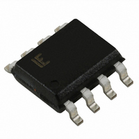
SP723AB Littelfuse Inc, SP723AB Datasheet - Page 2

SP723AB
Manufacturer Part Number
SP723AB
Description
TVS ARRAY ESD 6 INPUT 8-SOIC
Manufacturer
Littelfuse Inc
Series
SP723r
Datasheet
1.SP723AB.pdf
(6 pages)
Specifications of SP723AB
Package / Case
8-SOIC (3.9mm Width)
Voltage - Working
30V
Technology
Mixed Technology
Number Of Circuits
6
Applications
General Purpose
Current Rating
+/- 7 A
Forward Voltage Drop
2 V
Operating Voltage
2 V to 30 V
Channels
6 Channels
Capacitance
5 pF
Operating Temperature Range
- 40 C to + 105 C
Lead Free Status / RoHS Status
Contains lead / RoHS non-compliant
Power (watts)
-
Voltage - Clamping
-
Lead Free Status / RoHS Status
Lead free / RoHS Compliant, Contains lead / RoHS non-compliant
Other names
F2167
Available stocks
Company
Part Number
Manufacturer
Quantity
Price
Part Number:
SP723ABG
Manufacturer:
LITTELFUSE/力特
Quantity:
20 000
Part Number:
SP723ABTG
Manufacturer:
LITTELFUSE/力特
Quantity:
20 000
TVS Diode Arrays
Electronic Protection Array for ESD and Overvoltage Protection
Absolute Maximum Ratings
Continuous Supply Voltage, (V+) - (V-). . . . . . . . . . . . . . . . . . . . . . . . . +35V
Forward Peak Current, I IN to V CC , I IN to GND
Peak Pulse Current, 8/20µs. . . . . . . . . . . . . . . . . . . . . . . . . . . . . . . . . . . ±7A
ESD Ratings and Capability (Figure 1, Table 1)
Load Dump and Reverse Battery (Note 2)
CAUTION: Stresses above those listed in “Absolute Maximum Ratings” may cause permanent damage to the device. This is a stress only rating and operation of the device
at these or any other conditions above those indicated in the operational sections of this specification is not implied.
NOTE:
Electrical Specification
ESD Capability
ESD capability is dependent on the application and defined test
standard.The evaluation results for various test standards and methods
based on Figure 1 are shown in Table 1.
The SP723 has a Level 4 HBM capability when tested as a device to the
IEC 61000-4-2 standard. Level 4 specifies a required capability greater
than 8kV for direct discharge and greater than 15kV for air discharge.
For the “Modified” MIL-STD-3015.7 condition that is defined as an “in-
circuit” method of ESD testing, the V+ and V- pins have a return path to
ground and the SP723 ESD capability is typically greater than 25kV from
100pF through 1.5kΩ. By strict definition of MIL-STD-3015.7 using “pin-
to-pin” device testing, the ESD voltage capability is greater than 10kV.
For the SP723 EIAJ IC121 Machine Model (MM) standard, the ESD capa-
bility is typically greater than 2kV from 200pF with no series resistance.
SP723
(Refer to Figure 6). . . . . . . . . . . . . . . . . . . . . . . . . . . . . . . . . . ±4A, 100µs
1.
θ
JA is measured with the component mounted on an evaluation PC board in free air.
T A =40
o
C to 105
o
C, V IN = 0.5V CC , Unless Otherwise Specified
w w w . l i t t e l f u s e . c o m
Thermal Resistance (Typical, Note 1)
Storage Temperature Range . . . . . . . . . . . . . . . . . . . . . . . . . . . . -65
Maximum Junction Temperature. . . . . . . . . . . . . . . . . . . . . . . . . . . . . . 150
Lead Temperature (Soldering 10s). . . . . . . . . . . . . .. . . . . . . . . . . . . . 300
Thermal Information
PDIP Package . . . . . . . . . . . . . . . . . . . . . . . . . . . . . . . . . . . . . . . . . . . .160
SOIC Package . . . . . . . . . . . . . . . . . . . . . . . . . . . . . . . . . . . . . . . . . . . 170
(SOIC - Lead Tips Only)
IEC 1000-4-2
(Level 4)
MIL-STD-3015.7 Modified HBM
EIAJ IC121
STANDARD
SUPPLY
°±V
H.V.
FIGURE 1. ELECTROSTATIC DISCHARGE TEST
D
TABLE 1. ESD TEST CONDITIONS
CHARGE
SWITCH
HBM, Air Discharge
HBM, Direct Discharge
Standard HBM
Machine Model
MIL-STD-3015.7: R
IEC 1000-4-2: R
TYPE/MODE
R
1
1
C
50 to 100MΩ
1
D
1 to 10MΩ
R
D
1.5kΩ 100pF 25kV
1.5kΩ 100pF 10kV
330Ω 150pF 15kV
330Ω 150pF
DISCHARGE
0kΩ
R
SWITCH
D
200pF
C
D
DUT
IN
θ JA (
o
±V
C to 150
8kV
2kV
241
D
o
C/W)
o
o
o
C
C
C
5


