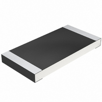
CRCW25120000Z0EG Vishay, CRCW25120000Z0EG Datasheet - Page 7

CRCW25120000Z0EG
Manufacturer Part Number
CRCW25120000Z0EG
Description
RES 0.0 OHM 1W 2512 SMD
Manufacturer
Vishay
Series
CRCWr
Type
Thick Filmr
Specifications of CRCW25120000Z0EG
Resistance
0 Ohms
Power Rating
1 Watt
Voltage Rating
500 Volts
Operating Temperature Range
- 55 C to + 155 C
Resistance (ohms)
0.0
Power (watts)
1W
Composition
Thick Film
Tolerance
Jumper
Size / Dimension
0.248" L x 0.124" W (6.30mm x 3.15mm)
Height
0.024" (0.60mm)
Lead Style
Surface Mount (SMD - SMT)
Package / Case
2512 (6432 Metric)
Resistance In Ohms
0.0
Case
2512 (6432 metric)
Termination Style
SMD/SMT
Dimensions
3.15 mm W x 6.3 mm L x 0.6 mm H
Product
Thick Film Resistors Zero-Ohm
Resistor Element Material
Thick Film
Resistor Case Style
2512
No. Of Pins
2
Power Rating(s)
Not RequiredW
Tolerance (+ Or -)
Not Required
Temperature Coefficient
Not Required
Operating Temp Range
-55C to 155C
Case Style
Molded
Failure Rate
Not Required
Product Length (mm)
6.3mm
Product Depth (mm)
3.15mm
Product Height (mm)
0.6mm
Construction
Rectangular
Lead Free Status / RoHS Status
Lead free / RoHS Compliant
Features
-
Temperature Coefficient
-
Lead Free Status / Rohs Status
Lead free / RoHS Compliant
Other names
541-0.0XTR
CRCW2512 0R0 E67 E3
CRCW2512 0R0 E67 E3
All tests are carried out in accordance with the following specifications:
• EN 60115-1, generic specification
• EN 140400, sectional specification
• EN 140401-802, detail specification
• IEC 60068-2, environmental test procedures
Packaging of components is done in paper or blister tapes according to IEC 60286-3.
Document Number: 20035
Revision: 02-Dec-10
TEST PROCEDURES AND REQUIREMENTS
EN
60115-1
CLAUSE
4.18.2
4.35
4.24
4.25.3
4.40
4.29
4.30
4.22
4.37
4.27
METHOD
78 (Cab)
60068-2
45 (XA)
45 (XA)
58 (Td)
TEST
6 (Fc)
IEC
-
-
-
-
-
Vibration, endurance
(human body model)
Component solvent
Solvent resistance
needle flame test
Single pulse high
voltage overload,
Periodic electric
upper category
soldering heat
Resistance to
Endurance at
10 µs/700 µs
by sweeping
steady state
temperature
Electrostatic
Flamability,
Damp heat,
of marking
resistance
discharge
overload
Lead (Pb)-Free Thick Film, Rectangular Chip Resistors
TEST
For technical questions, contact:
Stability for product types:
ESD voltage acc. to size
f = 10 Hz to 2000 Hz;
U =
Û = 10 x
Solder bath method
10 sweeps per axis
0.1 s on; 2.5 s off;
Isopropyl alcohol;
Isopropyl alcohol;
50 °C; method 1,
IEC 60695-11-5;
50 °C; method 2
x, y, z ≤ 1.5 mm;
IEC 61340-3-1;
(93 ± 3) % RH;
155 °C, 1000 h
3 pos. + 3 neg.
PROCEDURE
A ≤ 200 m/s
(260 ± 5) °C;
1000 cycles
(40 ± 2) °C;
discharges;
≤ 2 x U
≤ 2 x U
toothbrush
(10 ± 1) s
10 pulses
15 x P
56 days
10 s
D/CRCW e3
P
max.
max.
70
70
;
;
2
x R
x R
;
thickfilmchip@vishay.com
± (0.25 % R + 0.05 Ω) ± (0.5 % R + 0.05 Ω)
± (0.25 % R + 0.05 Ω) ± (0.5 % R + 0.05 Ω) ± (0.5 % R + 0.05 Ω)
± (1 % R + 0.05 Ω)
1 Ω to 10 MΩ
OR BETTER
STABILITY
CLASS 1
SIZE 0402 to 2512
± (1 % R + 0.05 Ω)
PERMISSIBLE CHANGE (ΔR)
No burning after 30 s
± (1 % R + 0.05 Ω)
± (1 % R + 0.05 Ω)
± (1 % R + 0.05 Ω)
No visible damage
REQUIREMENTS
no visible damage
± (2 % R + 0.1 Ω)
Marking legible,
1 Ω to 10 MΩ
OR BETTER
STABILITY
CLASS 2
D/CRCW e3
± (1 % R + 0.05 Ω)
REQUIREMENTS
± (2 % R + 0.1 Ω)
± (2 % R + 0.1 Ω)
CHANGE (ΔR/R)
PERMISSIBLE
10 Ω to 1 MΩ
SIZE 0201
www.vishay.com
Vishay
117


