V175LA2 Littelfuse Inc, V175LA2 Datasheet - Page 4
V175LA2
Manufacturer Part Number
V175LA2
Description
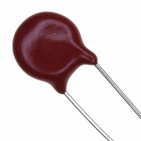
VARISTOR 175V 15J 7MM RADIAL ZA
Manufacturer
Littelfuse Inc
Series
LAr
Datasheet
1.V250LA2P.pdf
(13 pages)
Specifications of V175LA2
Energy
15J
Varistor Voltage
303V
Current-surge
1.2kA
Number Of Circuits
1
Maximum Ac Volts
175VAC
Maximum Dc Volts
225VDC
Package / Case
Disc 7mm
Technology
Metal Oxide
Capacitance Value
130pF
Clamping Current
10A
Clamping Voltage
455V
Lead Style
Radial
Ac Voltage Rating (max)
175VAC
Dc Voltage Rating (max)
225VDC
Operating Temp Range
-55C to 85C
Mounting
Through Hole
Surge Current (max)
1200A
Lead Spacing
6mm
Product Depth (mm)
5.6mm
Product Height (mm)
12mm
Product Diameter (mm)
9mm
Product
MOV
Voltage Rating Dc
225 V
Voltage Rating Ac
175 V
Peak Surge Current
1.2 KA
Surge Energy Rating
15 J
Capacitance
130 pF
Operating Temperature Range
- 55 C to + 85 C
Dimensions
7 mm Dia.
Termination Style
Radial
Lead Free Status / RoHS Status
Lead free / RoHS Compliant
Lead Free Status / RoHS Status
Compliant, Lead free / RoHS Compliant
Available stocks
Company
Part Number
Manufacturer
Quantity
Price
Company:

Part Number:
V175LA20AP
Manufacturer:
LITTELFUSE
Quantity:
32 000
Company:
Part Number:
V175LA2P
Manufacturer:
LITTELFUSE
Quantity:
32 000


LA Varistor Series
Power Dissipation Ratings
Should transients occur in rapid succession, the average
power dissipation is the energy (watt-seconds) per pulse
times the number of pulses per second. The power so
developed must be within the specifications shown on the
Device Ratings and Specifications Table for the specific
device.The operating values of a MOV need to be derated
at high temperatures as shown in the diagram below.
Because varistors only dissipate a relatively small amount
of average power they are not suitable for repetitive
applications that involve substantial amounts of average
power dissipation.
Current Energy and Power Derating Curve
Figure 1
100
90
80
70
60
50
40
30
20
10
0
-55
50
60
70
AMBIENT TEMPERATURE (
80
90
100
110
o
120
C)
Radial Lead Varistors > LA Series
130
140 150
Varistor Products
Revision: August 4, 2010
Peak Pulse Current Test Waveform
Figure 2
0
T = Time from 10% to 90% of Peak
T
T
Example - For an 8/20 μs Current Waveform:
1
1
2
= Virtual Origin of Wave
O
= Rise Time = 1.25 x T
= Decay Time
100
1
90
50
10
8μs = T
20μs = T
Please refer to www.littelfuse.com/series/la.html for current information.
1
2
= Rise Time
= Decay Time
T
T
1
T
2
Specifications are subject to change without notice.
TIME
©2010 Littelfuse, Inc.
Related parts for V175LA2
Image
Part Number
Description
Manufacturer
Datasheet
Request
R

Part Number:
Description:
FUSEHOLDER 20A MINI INLINE CRIMP
Manufacturer:
Littelfuse Inc
Datasheet:

Part Number:
Description:
FUSEHOLDER BODY ATO INLINE PNLMT
Manufacturer:
Littelfuse Inc
Datasheet:

Part Number:
Description:
FUSE 2A 63V FAST 1206
Manufacturer:
Littelfuse Inc
Datasheet:
Part Number:
Description:
FUSE 1.25A 63V FAST 1206
Manufacturer:
Littelfuse Inc
Datasheet:
Part Number:
Description:
FUSE .250A 125V FAST 1206
Manufacturer:
Littelfuse Inc
Datasheet:
Part Number:
Description:
FUSE 4A 32V FAST 1206
Manufacturer:
Littelfuse Inc
Datasheet:
Part Number:
Description:
FUSE 1.75A 63V FAST 1206
Manufacturer:
Littelfuse Inc
Datasheet:

Part Number:
Description:
FUSE 1A 32V FST 0603 LEADFREE TR
Manufacturer:
Littelfuse Inc
Datasheet:

Part Number:
Description:
FUSE 1A 32V FAST SLIM 0402
Manufacturer:
Littelfuse Inc
Datasheet:

Part Number:
Description:
FUSE 2A 125V FAST NANO2 SMD
Manufacturer:
Littelfuse Inc
Datasheet:

Part Number:
Description:
FUSE .250A 125V FAST NANO2 SMD
Manufacturer:
Littelfuse Inc
Datasheet:

Part Number:
Description:
FUSE .500A 125V FAST NANO2 SMD
Manufacturer:
Littelfuse Inc
Datasheet:

Part Number:
Description:
FUSE 1.5A 125V FAST NANO2 SMD
Manufacturer:
Littelfuse Inc
Datasheet:

Part Number:
Description:
FUSE 4A 125V FAST NANO2 SMD
Manufacturer:
Littelfuse Inc
Datasheet:

Part Number:
Description:
FUSE 1A 125V FAST NANO2 SMD
Manufacturer:
Littelfuse Inc
Datasheet: