DLP-USB245R DLP Design Inc, DLP-USB245R Datasheet - Page 6
DLP-USB245R
Manufacturer Part Number
DLP-USB245R
Description
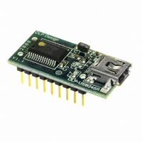
MODULE USB-TO-PARL FIFO 18-DIP
Manufacturer
DLP Design Inc
Datasheet
1.DLP-USB245R.pdf
(13 pages)
Specifications of DLP-USB245R
Convert From (adapter End)
USB
Convert To (adapter End)
Parallel
Features
Bi-Directional
Interface Type
USB
Operating Supply Voltage
3.3 V to 5.25 V
Product
Interface Modules
For Use With/related Products
Windows® 98 or higher, Mac OS 8.5 or higher
Lead Free Status / RoHS Status
Lead free / RoHS Compliant
Lead Free Status / RoHS Status
Lead free / RoHS Compliant, Lead free / RoHS Compliant
Other names
813-1025


5.0 EEPROM WRITE UTILITY
The DLP-USB245R has the option to accept manufacturer-specific information that is written
into EEPROM memory. Parameters that can be programmed include the VID and the PID
identifiers, the manufacturer's product string and a serial number.
MPROG is the latest EEPROM programming utility for the FT245R device. You must install the
latest release of the CDM drivers in order to run this application. If you have CDM drivers
installed on the PC that is to perform the EEPROM write process, you can run MPROG and
update the EEPROM contents with either mode (VCP or D2XX) active.
6.0 QUICK START GUIDE
This guide requires the use of a Windows XP/Vista PC that is equipped with a USB port.
1. Download the CDM device drivers from either www.dlpdesign.com or www.ftdichip.com.
2. Connect the DLP-USB245R board to the PC via a USB ‘A’ to mini-B cable. This action
At this point, the DLP-USB245R is ready for use. Note that the DLP-USB245R will appear non-
responsive if data sent from the host PC is not read from the FT245R device by an attached
microcontroller, microprocessor, DSP, FPGA, ASIC, etc.
7.0 PINOUT DESCRIPTION
Rev. 1.0 (November 2008)
Unzip the drivers into a folder on the hard drive.
initiates the loading of the USB drivers. When prompted, select the folder where the device
drivers were stored in Step 1. Windows will then complete the installation of the device
drivers for the DLP-USB245R module. The next time the DLP-USB245R module is
attached, the host PC will immediately load the correct drivers without any prompting.
Reboot the PC if prompted to do so.
(Interface Headers on bottom of PCB)
Pin 9
Pin 1
Top View
6
USB
Pin 18
Pin 10
© DLP Design, Inc.
Related parts for DLP-USB245R
Image
Part Number
Description
Manufacturer
Datasheet
Request
R

Part Number:
Description:
Interface Modules & Development Tools Dual Ch USB Adapter w/ FTDI FT2232H
Manufacturer:
DLP Design Inc
Datasheet:

Part Number:
Description:
Interface Modules & Development Tools USB to MSP430 w/ FTDI FT2232H
Manufacturer:
DLP Design Inc
Datasheet:

Part Number:
Description:
MODULE USB SECURITY DONGLE
Manufacturer:
DLP Design Inc
Datasheet:

Part Number:
Description:
MODULE USB-TO-UART/FIFO HS 18DIP
Manufacturer:
DLP Design Inc
Datasheet:

Part Number:
Description:
MODULE USB ADAPTER FOR FT2232D
Manufacturer:
DLP Design Inc
Datasheet:

Part Number:
Description:
MODULE USB-TO-FPGA TOOL W/MANUAL
Manufacturer:
DLP Design Inc
Datasheet:
Part Number:
Description:
Interface Modules & Development Tools RETRACTABLE USB CBL USB TO MINI USB
Manufacturer:
DLP Design Inc
Part Number:
Description:
Interface Modules & Development Tools USB FPGA Module w/ Xilinx XC3S400A
Manufacturer:
DLP Design Inc
Datasheet:

Part Number:
Description:
MODULE USB-TO-SRL UART 18-DIP
Manufacturer:
DLP Design Inc
Datasheet:

Part Number:
Description:
MODULE USB ADAPTR FOR FT2232D LP
Manufacturer:
DLP Design Inc
Datasheet:

Part Number:
Description:
MODULE USB-MCU FT245RL W/16F877A
Manufacturer:
DLP Design Inc
Datasheet:

Part Number:
Description:
MODULE USB-TO-FPGA TRAINING TOOL
Manufacturer:
DLP Design Inc
Datasheet:

Part Number:
Description:
MODULE USB-MCU FT232R W/18F2410
Manufacturer:
DLP Design Inc
Datasheet:

Part Number:
Description:
MODULE USB-MCU FT245RL W/SX48
Manufacturer:
DLP Design Inc
Datasheet:

Part Number:
Description:
MODULE USB-MCU FT2232D W/16F877A
Manufacturer:
DLP Design Inc
Datasheet: