USB-COM485-PLUS-2 FTDI, Future Technology Devices International Ltd, USB-COM485-PLUS-2 Datasheet
USB-COM485-PLUS-2
Specifications of USB-COM485-PLUS-2
USB-COM485-PLUS-2


Related parts for USB-COM485-PLUS-2


USB-COM485-PLUS-2 Summary of contents
Page 1
... Future Technology Devices International Ltd USB-COM485-PLUS2 Document Reference No.: FT_000136 Future Technology Devices International Ltd (FTDI) Unit 1, 2 Seaward Place, Centurion Business Park, Glasgow, G41 1HH, United Kingdom Tel.: +44 (0) 141 429 2777 E-Mail (Support): support1@ftdichip.com Web: http://www.ftdichip.com Neither the whole nor any part of the information contained in, or the product described in this manual, may be adapted or reproduced in any material or electronic form without the prior written consent of the copyright holder ...
Page 2
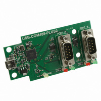
... TXD/RXD LEDs to provide a visual indication of data traffic through the module. Figure 1.1 USB-COM485-PLUS2 The module uses a standard USB-B device connector for connection to an upstream host or hub port. RS485-level signals are available on an industry-standard DE-9P connector. The maximum RS485-level data rate is 10Mbps. ...
Page 3
... LED Description The USB-COM485-PLUS2 uses three LEDs to indicate a valid link as well as data traffic according to the following table: LED Colour Function Yellow x 1 Power TxD Activity Red x 2 RxD Activity Green x 2 Table 1.1 – LED Description 1.3 Block Diagram USB B ...
Page 4
... Features Adds dual RS-485 serial port by connecting to a USB 2.0 Hi-Speed interface. Easy plug & play installation and RS-485 device connection Operates with USB 1.1 & 2.0 Host and Hub ports Industry Standard FTDI chip set & device drivers for maximum compatibility ® ...
Page 5
... Example Applications and Configurations ..................................................... 6 2.1.1 Wiring ...................................................................................................... 6 2.2 Device Driver Installation ............................................................................. 7 2.2.1 Microsoft Windows ..................................................................................... 7 2.2.2 Mac OS X, Linux, Windows CE ................................................................... 11 3 Connections .................................................................................. 12 3.1 External Connectors .................................................................................... 12 3.1.1 USB ....................................................................................................... 12 3.1.2 RS485 .................................................................................................... 13 4 Electrical details ........................................................................... 14 4.1 USB ............................................................................................................. 14 4.2 RS485 ......................................................................................................... 14 4.3 Power Output .............................................................................................. 14 5 Mechanical Details ........................................................................ 15 5.1 Module Mechanical Dimensions ...
Page 6
... Appendix A - List of Figures and tables......................................... 22 Appendix B - Revision History ............................................................ 23 Copyright © 2010 Future Technology Devices International Limited Document Reference No.: FT_000136 USB-COM485-PLUS2 Datasheet Version 1.2 Clearance No.: FTDI#104 5 ...
Page 7
... Installation 2.1 Example Applications and Configurations 2.1.1 Wiring Insert the A-plug into an available USB Host or Hub port. Insert the mini-B-plug into the USB mini-B- receptacle on the USB-COM485-PLUS2. DTE Pin Number Signal Name 1 DATA- = Transmit/Receive Data, negative polarity Also Terminator 2 2 DATA+ = Transmit/Receive ...
Page 8
... Installation Executable shown on Windows XP 1) Login to your system as Administrator user with Administrator rights. 2) Prior to connecting the USB-COM485-PLUS2 to the USB Host or Hub port, download the latest device driver version from the FTDIChip web site. 3) Run this executable to install the device drivers. ...
Page 9
... After the files are found and installed, click “Finish” to complete the installation. Figure 2.5 - Complete Hardware Installation 7) Steps 2 through 6 will repeat. The first time installs the basic USB Serial Converter in the USB device tree. The second time installs the Virtual COM Port layer in the Ports tree and assigns the COM port number ...
Page 10
... And two additional “USB Serial Converter A” and “USB Serial Converter B”. Figure 2.8 - COM Port and USB Device name Assignment To determine which COM port has been assigned to Converter the cursor point to the USB Serial Port (COM10) or (COM11), then right-click on it and select “Properties”, it shows their relationship to the Converter ...
Page 11
... Figure 2.9 – COM Port Assignment and Properties Use this COM port number with your application software in order to access the USB-COM485-PLUS2 application requires use of a different COM port number, the assignment may be changed through the Advanced Driver Options settings. From the above “Properties”, click on the “Port Settings” tab. ...
Page 12
... Device drivers and FTDI installation guides for Mac OS X, Linux and Windows CE are available for download on the FTDIChip web sites. Follow the respective FTDI installation guides for the chosen operating system. Copyright © 2010 Future Technology Devices International Limited Document Reference No.: FT_000136 USB-COM485-PLUS2 Datasheet Version 1.2 Clearance No.: FTDI#104 11 ...
Page 13
... Connections 3.1 External Connectors 3.1.1 USB The USB-COM485-PLUS2 is a downstream USB 2.0 Device. A standard USB mini type “B” receptacle is mounted inside the USB-COM485-PLUS2 to facilitate connection to an upstream USB Host or Hub. Pin Number Pin Type 1 Power Bidirectional 2 3 Bidirectional Ground Shield Case Ground Table 3.1 – ...
Page 14
... The RS485 ports are configured as Data Terminal Equipment (DTE), with a 9-contact D-Sub Pin connector. Pin assignments are according to TIA/EIA-485. In addition, pin9 of DB9 provides +5VDC to an external device with a maximum current draw of 450mA once the USB-COM485-PLUS2 has been enumerated by the system. Both D-type connectors have a similar connection as described in Table 3.2. ...
Page 15
... Power Output The USB-COM485-PLUS2 provides +5V DC for an external device that requires power on pin9 of DB9. The maximum allowable current is 500mA, including the circuitry of the USB-COM485-PLUS2 itself 450mA may be used by the external device. The +5V output is only enabled when the USB interface is not in suspend. Parameter ...
Page 16
... Module Mechanical Dimensions Dimensions are in mm. The PCB height is dominated by the D-type connectors and is 17mm +/- 2mm (this includes the tails of the D-type connectors soldered pins). Figure 5.1 - USB-COM485-PLUS2 PCB Dimensions Copyright © 2010 Future Technology Devices International Limited Document Reference No.: FT_000136 USB-COM485-PLUS2 Datasheet Version 1 ...
Page 17
... Operating Temperature T Range Table 6.2 - Operating Temperature Copyright © 2010 Future Technology Devices International Limited Minimum Typical Maximum -65 +150 Minimum Typical Maximum –40 +85 Document Reference No.: FT_000136 USB-COM485-PLUS2 Datasheet Version 1.2 Clearance No.: FTDI#104 Units Conditions o C Units Conditions 5% to 95% RH non condensing 16 ...
Page 18
... EMI Compatibility FCC and CE The USB-COM485-PLUS2 has been tested to be compliant with both FCC Part 15 Subpart B and European EMC Directive. NOTE: This is a Class B product domestic environment, this product may cause radio interference, in which case the user may be required to take adequate measures. ...
Page 19
... Import / Export Information Country of Origin China TBD Harmonized Code Product Description USB to RS485 Development Module, Dual Port USA ECCN EAR99 – No License Required Table 7.1 - Import / Export Information Copyright © 2010 Future Technology Devices International Limited Document Reference No.: FT_000136 USB-COM485-PLUS2 Datasheet Version 1 ...
Page 20
... Computer power Computer is not in Sleep or Standby - If a USB Hub is used, be sure it is set for “Self-Powered” operation - If a USB Hub is used, be sure all cables are properly inserted - If all the above are OK, the Yellow LED should be lit, indicating the device has been recognized by the USB subsystem. RS485 cables – ...
Page 21
... USA Tel: +1 (503) 547 0988 Fax: +1 (503) 547 0987 E-Mail (Sales) us.sales@ftdichip.com E-Mail (Support) us.support@ftdichip.com E-mail (General Enquiries) us.admin@ftdichip.com Web Site URL http://www.ftdichip.com Copyright © 2010 Future Technology Devices International Limited Document Reference No.: FT_000136 USB-COM485-PLUS2 Datasheet Version 1.2 Clearance No.: FTDI#104 20 ...
Page 22
... Distributor and Sales Representatives Please visit the Sales Network page of the FTDI Web site for the contact details of our distributor(s) and sales representative(s) in your country. Copyright © 2010 Future Technology Devices International Limited Document Reference No.: FT_000136 USB-COM485-PLUS2 Datasheet Version 1.2 Clearance No.: FTDI#104 21 ...
Page 23
... Figure 2.4 – Automatic Install ......................................................................................................................... 8 Figure 2.5 - Complete Hardware Installation ................................................................................................ 8 Figure 2.6 - Hardware Ready .......................................................................................................................... 8 Figure 2.7 - Device Manager ........................................................................................................................... 9 Figure 2.8 - COM Port and USB Device name Assignment ......................................................................... 9 Figure 2.9 – COM Port Assignment and Properties ................................................................................... 10 Figure 2.10 - Settings Tab ............................................................................................................................. 10 Figure 2.11 - Advanced Options ................................................................................................................... 11 Figure 5 ...
Page 24
... Version 1.2 Edited Section 1.3.1, Removed the statement “A standard “A to B” cable is provided” Copyright © 2010 Future Technology Devices International Limited Document Reference No.: FT_000136 USB-COM485-PLUS2 Datasheet Version 1.2 Clearance No.: FTDI#104 6th July 2009 27th August 2009 25th January 2010 ...