ZU-1890M Panasonic - ATG, ZU-1890M Datasheet - Page 6
ZU-1890M
Manufacturer Part Number
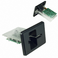
ZU-1890M
Description
CARD READER FULL INSERT 2 TRACK
Manufacturer
Panasonic - ATG
Datasheet
1.ZU-1890M.pdf
(10 pages)
Specifications of ZU-1890M
Card Reader Type
Magnetic, Push/Pull
Interface
TTL
Card Read/write Type And Tracks
Magnetic - Read Tracks 1,2
Card Reading Direction
Ejection
Card Standard
ISO 7810, ISO 7811
Card Speed
10 ~ 150 mm/s
Supply Voltage
4.5 V ~ 5.5 V
Lead Free Status / RoHS Status
Contains lead / RoHS non-compliant
Other names
PCR111
ZU1890M
ZU1890M


7.3 Explanation of output signal
7.4 Output signal timing chart
7.5 Terminal No. of connector
(1) /CLD
(2) /RCL 1,2
(3) /RDT 1,2
(4) /PH1
(1) Maker
The magnetic
Detail the /RCL & /RDT timing chart
The magnetic
/PH1
/CLD
/RCL
/RDT
head output
Bit data
(CARD LOAD)
head output
/RCL
/RDT
When the jitter of the magnetic head output is 0% , the following equation is satisfied.
Output signals are /CLD, /RCL1,2, /RDT1,2, /PH1 and effective operation mode for each of these
signals shall be ”L” level for all.
(READ CLOCK)
(READ DATA)
(SENSOR)
T (s)=
T=T
1
=T
Recording density (BPI)
: The /CLD will be Low when a Magnetic Card is running in the Magnetic
: This is used to sample the data line by its falling edges.
: At the moment /RCL change from High to Low; /RDT is “1” when the /RDT is
: /PH1 will be Low when a Magnetic Card is inserted in the end of Magnetic
2
The /CLD will be High when the Card is stopped or not present in the Card reader.
The time relationship of the clock with respect to the order signals is shown
in Figure 7.4.
Low , and /RDT is “0” when the /RDT is High.
Card Reader.
=T
Card Reader.
3
2.54 cm/inch
, t1=t2
Card Insertion
“0”
0
T
: HONDA
1
Fig 7.4.1 Timing Sequence
2/3T
T
t1
2
“1”
1
1
t2
×
2/3T
- 4 -
“0”
T
3
Card speed(cm/s)
2
0
1
“0”
0
“1”
1
Card Ejection
Indefinite signals
MAX.30 ms
All “0”
Related parts for ZU-1890M
Image
Part Number
Description
Manufacturer
Datasheet
Request
R

Part Number:
Description:
CARD READER FULL INSERT DBL TRK
Manufacturer:
Panasonic - ATG


Part Number:
Description:
CARD READER 3 TRACK SWIPE
Manufacturer:
Panasonic - ATG
Datasheet:

Part Number:
Description:
CARD READER 1 TRACK SWIPE LL HD
Manufacturer:
Panasonic - ATG
Datasheet:

Part Number:
Description:
CARD READER SNG TRACK MAN SWIPE
Manufacturer:
Panasonic - ATG
Datasheet:

Part Number:
Description:
CARD READER HALF INSERT 1 TRACK
Manufacturer:
Panasonic - ATG

Part Number:
Description:
CARD READER FULL INSERT 2 TRACK
Manufacturer:
Panasonic - ATG

Part Number:
Description:
CARD READER HALF INSERT W/BEZEL
Manufacturer:
Panasonic - ATG


Part Number:
Description:
CARD READER 2 HEAD INSERT RS232
Manufacturer:
Panasonic - ATG

Part Number:
Description:
CARD READER FULL INSERT USB
Manufacturer:
Panasonic - ATG
Datasheet:


Part Number:
Description:
CARD READER 3 TRACK + SMART CARD
Manufacturer:
Panasonic - ATG