TNPW080510K0BETA Vishay, TNPW080510K0BETA Datasheet

RES 10.0K OHM 1/8W 0.1% 0805

TNPW080510K0BETA

Manufacturer Part Number
TNPW080510K0BETA
Description
RES 10.0K OHM 1/8W 0.1% 0805
Manufacturer
Vishay
Series
TNPWr
Type
Thin Filmr

Specifications of TNPW080510K0BETA

Resistance
10kohm
Temperature Coefficient
±25ppm/°C
Resistance (ohms)
10K
Power (watts)
0.125W, 1/8W
Composition
Thin Film
Tolerance
±0.1%
Size / Dimension
0.079" L x 0.049" W (2.00mm x 1.25mm)
Height
0.018" (0.45mm)
Lead Style
Surface Mount (SMD - SMT)
Package / Case
0805 (2012 Metric)
Resistance In Ohms
10.0K
Case
0805 (2012 metric)
Power Rating(s)
1/8 or 1/10W
Tolerance (+ Or -)
0.1%
Mounting Style
Surface Mount
Operating Temp Range
-55C to 155C
Case Style
Molded
Military Standard
Not Required
Failure Rate
Not Required
Product Length (mm)
2mm
Product Depth (mm)
1.24mm
Product Height (mm)
0.4mm
Resistance Tolerance
± 0.1%
Power Rating
125mW
Voltage Rating
100V
Resistor Element Material
Thin Film
Lead Free Status / RoHS Status
Contains lead / RoHS non-compliant
Features
-
Lead Free Status / RoHS Status
Contains lead / RoHS non-compliant, Contains lead / RoHS non-compliant
Other names
TNPW0805 10K 0.1% T9 RT1
3)
TNPW
Vishay Dale
TNPW Precision Thin Film Flat Chip Resistors are the
perfect choice for most fields of modern electronics where
reliability and stability is of major concern. Typical
applications include telecommunication, industrial, medical
equipment, high-end computer and audio/video electronics.
1)
2)
• Extended values available on request
www.vishay.com
66
PARAMETER
Rated Dissipation at 70°C
(EN-140401-801 | EIA 575)
Limiting Element Voltage
Thermal Resistance
Insulation Resistance
Category Temperature Range
Failure Rate
Weight / 1000pcs
Measuring conditions in acc. with EN 140401-801
TECHNICAL SPECIFICATIONS
STANDARD ELECTRICAL SPECIFICATIONS
TNPW0402
TNPW0603
TNPW0805
TNPW1206
TNPW1210
TNPW2010
TNPW2512
±1% resistors are only available in E24/E96
Size not specified in EN-140401-801
TYPE
EN 140401-801
3)
0.063
0.100
0.125
0.250
0.33
0.40
0.50
POWER RATING P
4)
2)
2)
2)
Thin Film, Rectangular, Resistor Chips
UNIT
V P
K/W
W
h
°C
g
–1
0.063 0.063
- 870
EIA 575
0.063
0.063
0.100
0.125
0.250
0.400
0.500
TNPW0402
For Technical Questions, contact: ff3aresistors@vishay.com
25
0.65
70°C
(W)
- 550
0.1
TNPW0603
75
RESISTANCE
2
RANGE (∆ ∆ ∆ ∆ ∆ )
10R - 3M01
47R - 2M13
10R - 4M99
10R - 8M87
10R - 100K
47R - 100K
10R - 332K
47R - 332K
10R - 1M0
47R - 1M0
10R - 2M0
47R - 2M0
47R - 1M0
47R - 1M0
0.063 0.125
4)
Rated voltage:
- 440
TNPW0805
100
5.5
FEATURES
• Metal film layer on high quality ceramic
• Protective top coat
• Available with tin lead or lead (Pb)-free solder contacts
• Excellent stability at different environmental conditions
• Low temperature coefficient and tight tolerances
APPLICATIONS
• Automotive
• Telecommunication
• Medical Equipment
• Industrial Equipment
• Power rating depends on the max. temperature at the solder point,
• TNPW 0402 without marking
- 55 / + 125 (+ 155)
the component placement density and the substrate material
0.1
COEFFICIENT (ppm/K)
± 10, ± 15, ± 25, ± 50
± 10, ± 15, ± 25, ± 50
0.3 •10
TEMPERATURE
Px R
> 10
- 220
0.25
TNPW1206
± 25, ± 50
± 25, ± 50
± 10, ± 15
± 25, ± 50
± 10, ± 15
± 25, ± 50
± 10, ± 15
± 25, ± 50
± 25, ± 50
± 25, ± 50
± 25, ± 50
± 25, ± 50
100
9
–9
10
0.125
- 140
0.33
TNPW1210
100
16
± 0.1%, ± 0.5%, ± 1%
± 0.1%, ± 0.5%, ± 1%
± 0.1%, ± 0.5%, ± 1%
0.25
± 0.5%, ± 1%
TOLERANCE
± 0.5%, ± 1%
± 0.5%, ± 1%
± 0.5%, ± 1%
± 0.1%
± 0.1%
± 0.1%
± 0.1%
± 0.1%
± 0.1%
± 0.1%
- 90
TNPW2010
Document Number 31006
150
28
0.4
Revision 15-Sep-05
1)
1)
1)
1)
- 70
TNPW2512
E-SERIES
24-192
24-192
24-192
24-192
24-192
24-192
24-192
200
39
0.5

Related parts for TNPW080510K0BETA

TNPW080510K0BETA Summary of contents
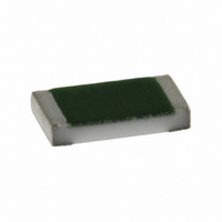
Page 1

... Rated voltage For Technical Questions, contact: ff3aresistors@vishay.com TOLERANCE ± 25, ± 50 ± 0.5%, ± 1% ± 0.1% ± 25, ± 50 ± 0.1%, ± 0.5%, ± 1% ± 10, ± 15 ± 0.1% ± 25, ± 50 ± 0.1%, ± 0.5%, ± 1% ± ...

Page 2

... H = ± 50 ppm ± 0 ± 25 ppm ± 1 ± 15 ppm ± 10 ppm/K 1002 B TOLERANCE B = ± 0 ± 0 ± 1.0 % For Technical Questions, contact: ff3aresistors@vishay.com Vishay Dale DIMENSIONS millimeters 0.5 ± 0.05 0.35 ± 0.05 0.81 ± 0.2 0.4 ± 0.1 1.24 ± 0.2 0.4 ± 1.6 ± ...

Page 3

... The pure tin plating of the Lead (Pb)-free resistors type, provides compatibility with Lead (Pb)-free and lead-containing soldering processes. The immunity of the plating against tin whisker growth has been proven under extensive testing. For Technical Questions, contact: ff3aresistors@vishay.com EIA EN -25 0 ...

Page 4

... HF Performance Frequency f in MHz For Technical Questions, contact: ff3aresistors@vishay.com Vishay Dale TNPW0603 TNPW0402 TNPW0805 1K 10K 100K Resistance Value in TNPW0603 5 10 ...

Page 5

... Secondary conditions ϑu - 70°C c) Û 0. Square Pulse Pulse Rating Square Pulse For Technical Questions, contact: ff3aresistors@vishay.com 100R 1K 10K Resistance Value in TNPW0805 TNPW0603 (permissible constant power at ϑu = 70°C) 70 see diagram (Max. pulse voltage) max - Square Pulse t 70 Document Number 31006 Revision 15-Sep-05 ...

Page 6

... EN140400 • EIA 575 • EN 140401-801 • EN 60115-1 • IEC 60286-3 Document Number 31006 Revision 15-Sep-05 Thin Film, Rectangular, Resistor Chips For Technical Questions, contact: ff3aresistors@vishay.com TNPW Vishay Dale TEST RESULTS TNPW0402 TO TNPW2512 TOLERANCES ± 0 ± 0.25 % < 100R • 100R ± ...

Related keywords