MMP200FRF33R Yageo, MMP200FRF33R Datasheet - Page 6
MMP200FRF33R
Manufacturer Part Number
MMP200FRF33R
Description
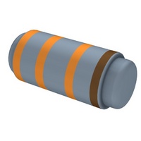
RES MELF METAL 33 OHM 2W 1%
Manufacturer
Yageo
Series
MMPr
Datasheet
1.MMP100FRF10R.pdf
(7 pages)
Specifications of MMP200FRF33R
Resistance (ohms)
33
Power (watts)
2W
Composition
Metal Film
Temperature Coefficient
±100ppm/°C
Tolerance
±1%
Size / Dimension
0.118" Dia x 0.335" L (3.00mm x 8.50mm)
Lead Style
Surface Mount (SMD - SMT)
Package / Case
MELF, 0309
Resistance In Ohms
33.0
Case
MELF
Lead Free Status / RoHS Status
Lead free / RoHS Compliant
Features
-
Height
-


(4) Insulation Resistance
(5) Solderability
(6) Resistance to Solvent
(7) Terminal Strength
(8) Pulse Overload
(9) Load Life in Humidity
(10) Load Life Test
(11) Temperature Cycling Test
Apply test terminal on lead and resistor body.
The test resistance should be high than 10,000M ohm.
Immerse the specimen into the solder pot at 260 ± 5 °C for 5 ± 0.5 seconds.
At least 95% solder coverage on the termination.
The specimen into the appropriate solvent of IPA condition of ultrasonic machine for 1 minutes.
The specimen is no deterioration of coatings and color code.
Direct Load – Resistors shall be held by one terminal and the load shall be gradually applied in the
direction of the longitudinal axis of the resistor unit the applied load reached 5 pounds。
The load shall be held for 10 seconds. The load of weight shall be ≧ 2.5 kg ( 24.5N ).
Apply 4 times of rated voltage to the specimen at the 1 second on and 25 seconds off cycle, subjected
to voltage application cycles specified in 10,000 time。
The change of the resistance value shall be within ± 1.0% + 0.05 Ω
Place the specimen in a test chamber at 40 ± 2 °C and 90 ~ 95 % relative humidity. Apply the rated
voltage to the specimen at the 1.5 hours on and 0.5 hour off cycle. The total length of test is 1,000 hours
The change of the resistance value shall be within ± 2.0 % + 0.1 Ω
Placed in the constant temperature chamber of 70 ± 3 °C the resistor shall be connected to the lead wire
at the point of 25mm. Length with each terminal, the resistors shall be arranged not much effected
mutually by the temperature of the resistors and the excessive ventilation shall not be performed, for 90
minutes on and 30 minutes off under this condition the rated D.C. voltage is applied continuously for
1000+48/-0 hours then left at no-load for 1hour, measured at this time the resistance value。
The change of the resistance value shall be within ± 2.0 % + 0.1 Ω.
There shall be no remarkable change in the appearance and the color code shall be legible after the test.
The temperature cycle shown in the following table shall be repeated 5 times consecutively. The
measurement of the resistance value is done before the first cycle and after ending the fifth cycle,
leaving in the room temperature for about 1 hour。
Temperature Cycling Conditions:
The change of the resistance value shall be within ± 0.75 % + 0.05 Ω
After the test the resistor shall be free from the electrical or mechanical damage.
Step
1
2
3
4
Temperature(°C)
155 ± 3
-55 ± 3
25 ± 3
25 ± 3
Page-6
Time (minute)
2 ~ 3
2 ~ 3
30
30
Related parts for MMP200FRF33R
Image
Part Number
Description
Manufacturer
Datasheet
Request
R

Part Number:
Description:
YAGEO 22pF ±5% 50V NPO
Manufacturer:
Yageo
Datasheet:
