Y145310K0000T9L Vishay, Y145310K0000T9L Datasheet

RES 10K OHM .6W .01% FOIL RAD

Y145310K0000T9L

Manufacturer Part Number
Y145310K0000T9L
Description
RES 10K OHM .6W .01% FOIL RAD
Manufacturer
Vishay
Series
Z201r
Datasheet

Specifications of Y145310K0000T9L
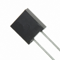
Resistance (ohms)
10K
Power (watts)
0.6W
Composition
Metal Foil
Features
Non-Inductive
Temperature Coefficient
±0.2ppm/°C
Tolerance
±0.01%
Size / Dimension
0.300" L x 0.105" W (7.62mm x 2.67mm)
Height
0.326" (8.28mm)
Lead Style
Through Hole
Package / Case
Radial
Resistance In Ohms
10.0K
Case
Radial
Lead Free Status / RoHS Status
Lead free / RoHS Compliant
Other names
Y1453-10K
Z201T 10K OHM 0.01%
INDUSTRY BREAKTHROUGH
INTRODUCTION
The Z201 (0.150" lead spacing) and Z201L (0.200" lead
spacing) Bulk Metal
breakthrough. This is the 3
resistors since the first Bulk Metal
introduced by in 1962. Each represents an improvement on
the earlier model. The TCR slope of the Z201 is 0.2 ppm/C
(- 55 °C to + 125 °C, + 25 °C ref.) and is an order of
magnitude better than the original S102C. The Bulk Metal
Z-Foil resistor is the ultimate choice in the most demanding
analog applications.
The Z-Foil technology provides a significant reduction of the
resistive component’s sensitivity to ambient temperature
variations (TCR) and applied power changes (PCR).
Designers can now guarantee a high degree of stability and
accuracy in fixed-resistor applications using solutions based
on Vishay’s revolutionary Z-Foil technology.
Our application engineering department is available to
advise and to make recommendations. For non-standard
technical requirements and special applications, please
contact us.
* Pb containing terminations are RoHS compliant, exemptions may apply
Document Number: 63113
Revision: 25-Mar-10
Any value at any tolerance available within resistance rage
TABLE 1 - TOLERANCE AND TCR VERSUS
VALUE
100  to 100 k
80  to < 100 
50  to < 80 
25  to < 50 
10  to < 25 
Ultra High Precision Z-Foil Resistor with TCR of ± 0.05 ppm/°C,
PCR of 5 ppm at Rated Power, Tolerance of ± 0.005 %
TOLERANCE
STANDARD
®
± 0.005 %
± 0.005 %
± 0.01 %
± 0.01 %
± 0.02 %
Z-Foil resistors represent an industry
rd
and Load Life Stability of ± 0.005 %
in a series of ultra-precision
MAXIMUM SPREAD
TYPICAL TCR AND
- 55 °C TO + 125 °C
± 0.2 ± 0.6 ppm/°C
± 0.2 ± 0.8 ppm/°C
± 0.2 ± 1.0 ppm/°C
± 0.2 ± 1.3 ppm/°C
± 0.2 ± 1.6 ppm/°C
®
(+ 25 °C REF.)
Foil resistor was
For any questions, contact:
®
FEATURES
 Temperature coefficient of resistance (TCR):
 Power coefficient of resistance “R due to self
 Rated power: 0.6 W at 70 °C
 Resistance tolerance: to ± 0.005 %
 Load life stability: to ± 0.005 % at 70 °C, 2000 h at rated
 Resistance range: 10  to 100 k (higher or lower values
 Electrostatic discharge (ESD) up to 25 000 V
 Non inductive, non capacitive design
 Rise time: 1.0 ns without ringing
 Current noise: 0.01: - 40 dB
 Thermal EMF: 0.1 µV/°C max.
 Voltage coefficient: < 0.1 ppm/V
 Non inductive: 0.08 µH
 Terminal finishes available:
 Maximum working voltage: 300 V
 Drop in replacement for S102C/K
 Matched sets are available per request
 For better performances please contact us
APPLICATIONS
 Precision amplifiers, high precision instrumentation,
 Laboratory, audio (high end stereo equipment)
 EB applications, military, airborne and space
 Down-hole (high temperature)
foil@vishaypg.com
FIGURE 1 - POWER DERATING CURVE
± 0.05 ppm/°C typical (0 °C to + 60 °C)
± 0.2 ppm/°C typical (- 55 °C to + 125 °C,
+ 25 °C ref.)
heating”: ± 5 ppm at rated power
power
of resistance available)
medical and automatic test equipment
200 %
175 %
150 %
125 %
100 %
75 %
50 %
25 %
0
- 75 - 50 - 25
- 55 °C
0.3 W at 125 °C
0.05 µV/°C typical
Ambient Temperature (°C)
0
+ 25 + 50 + 75 + 100 + 125 + 150 + 175 + 200
Vishay Foil Resistors
+ 70 °C
lead (Pb)-free
tin/lead alloy
Z201 (Z-Foil)
Double Rated Power
www.foilresistors.com
Rated Power
Safe operation
for < 150 ppm
ΔR after
2000 hours
load life
1

Related parts for Y145310K0000T9L

Y145310K0000T9L Summary of contents

Page 1

... Designers can now guarantee a high degree of stability and accuracy in fixed-resistor applications using solutions based on Vishay’s revolutionary Z-Foil technology. Our application engineering department is available to advise and to make recommendations. For non-standard technical requirements and special applications, please contact us ...

Page 2

... Z201 (Z-Foil) Vishay Foil Resistors FIGURE 2 - TRIMMING TO VALUES (conceptual illustration) Interloop Capacitance Reduction in Series Mutual Inductance Reduction due to Change in Current Direction Note: Foil shown in black, etched spaces in white FIGURE 4 - STANDARD IMPRINTING AND DIMENSIONS Front View L Date Code 07 VISHAY Year H XXXX Z201 ...

Page 3

... For any questions, contact: foil@vishaypg.com Z201 (Z-Foil) Vishay Foil Resistors Z201 MAXIMUM R TYPICAL R ± 0.01 % (100 ppm) ± 0.002 % (20 ppm) ± 0.01 % (100 ppm) ± 0.003 % (30 ppm) see Table 1 ± ...

Page 4

... Z201 (Z-Foil) Vishay Foil Resistors TABLE 4 - GLOBAL PART NUMBER INFORMATION NEW GLOBAL PART NUMBER: Y1453250R000V9L (preferred part number format) DENOTES PRECISION PRODUCT CODE 1453 = Z201 1454 = Z201L FOR EXAMPLE: ABOVE GLOBAL ORDER Y1453 250R000 TYPE: Z201 VALUE: 250.0  ABSOLUTE TOLERANCE: ± 0.005 % ...

Page 5

... Customers using or selling Vishay Precision Group products not expressly indicated for use in such applications do so entirely at their own risk and agree to fully indemnify Vishay Precision Group for any damages arising or resulting from such use or sale. Please contact authorized Vishay Precision Group personnel to obtain written terms and conditions regarding products designed for such applications ...

Related keywords