Y14531K00000T9L Vishay, Y14531K00000T9L Datasheet - Page 3
Y14531K00000T9L
Manufacturer Part Number
Y14531K00000T9L
Description
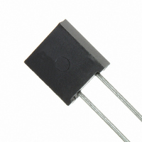
RES 1.0K OHM .6W .01% FOIL RAD
Manufacturer
Vishay
Series
Z201r
Datasheet
1.Y1453100R000T9L.pdf
(5 pages)
Specifications of Y14531K00000T9L
Resistance (ohms)
1K
Power (watts)
0.6W
Composition
Metal Foil
Features
Non-Inductive
Temperature Coefficient
±0.2ppm/°C
Tolerance
±0.01%
Size / Dimension
0.300" L x 0.105" W (7.62mm x 2.67mm)
Height
0.326" (8.28mm)
Lead Style
Through Hole
Package / Case
Radial
Resistance In Ohms
1.00K
Case
Radial
Rohs Compliant
YES
Resistance
1kohm
Resistance Tolerance
± 0.01%
Power Rating
600mW
Voltage Rating
300V
Resistor Element Material
Metal Foil
Lead Free Status / RoHS Status
Lead free / RoHS Compliant
Other names
Y1453-1.0K
Z201T 1K OHM 0.01%
Z201T 1K OHM 0.01%


STANDARD MEASUREMENT (at room temperature)
Standard Test Conditions:
Temperature: + 23 °C ± 2 °C
Relative humidity: 35 to 65 % RH
Lead test point: 0.5" (12.7 mm) from resistor body
IMPROVED PERFORMANCE TESTING
The preceding information is based on product directly off the production line. Improved performance (meaning increased time
stability with load and other stresses) is available through factory conducted "Improved Performance Testing". The test routine
is usually tailored to the user’s stability objectives. A screened product can be brought down to a potential load life drift of less
than 50 ppm.
For example, the datasheet “7 Technical Reasons to Specify BMF Resistive Components” shows the drift characteristics of a
standard product.
Various screen test routines are available and all anticipated stresses must be taken into account before settling on one specific
test routine. Our applications engineering department is available to discuss and recommend appropriate routines given the full
spectrum of anticipated stresses and stability requirements.
Document Number: 63113
Revision: 25-Mar-10
TABLE 3 - ENVIRONMENTAL PERFORMANCE COMPARISON
Test Group I
Thermal Shock
Short Time Overload
Test Group II
Resistance Temperature
Characteristic
Low Temperature Storage
Low Temperature Operation
Terminal Strength
Test Group III
DWV
Resistance to Solder Heat
Moisture Resistance
Test Group IV
Shock
Vibration
Test Group V
Life Test at 0.3 W/+ 125 °C
2000 hours
10 000 hours
Test Group Va
Life Test at 0.6 W (2 x Rated Power)/+ 70 °C, 2000 hours
Test Group VI
High Temperature Exposure
Test Group VII
Voltage Coefficient
For any questions, contact:
MIL-PRF-55182
± 25 ppm/°C
0.005 %/V
± 0.15 %
± 0.15 %
± 0.15 %
CHAR J
± 0.2 %
± 0.2 %
± 0.2 %
± 0.1 %
± 0.4 %
± 0.2 %
± 0.2 %
± 0.5 %
± 2.0 %
± 0.5 %
± 2.0 %
foil@vishaypg.com
± 0.015 % (150 ppm)
± 0.015 % (150 ppm)
± 0.01 % (100 ppm)
± 0.01 % (100 ppm)
± 0.01 % (100 ppm)
± 0.01 % (100 ppm)
± 0.01 % (100 ppm)
± 0.01 % (100 ppm)
± 0.01 % (100 ppm)
± 0.05 % (500 ppm)
± 0.01 % (100 ppm)
± 0.01 % (100 ppm)
± 0.05 % (500 ppm)
± 0.1 % (1000 ppm)
< 0.00001 %/V
MAXIMUM R
see Table 1
Vishay Foil Resistors
Z201
Z201 (Z-Foil)
± 0.002 % (20 ppm)
± 0.003 % (30 ppm)
± 0.002 % (20 ppm)
± 0.002 % (20 ppm)
± 0.002 % (20 ppm)
± 0.002 % (20 ppm)
± 0.005 % (50 ppm)
± 0.01 % (100 ppm)
± 0.002 % (20 ppm)
± 0.002 % (20 ppm)
± 0.01 % (100 ppm)
± 0.03 % (300 ppm)
± 0.01 % (100 ppm)
± 0.05 % (500 ppm)
(0 °C to + 60 °C)
www.foilresistors.com
< 0.00001 %/V
± 0.05 ppm/°C
TYPICAL R
3
Related parts for Y14531K00000T9L
Image
Part Number
Description
Manufacturer
Datasheet
Request
R

Part Number:
Description:
357-036-542-201 CARDEDGE 36POS DL .156 BLK LOPRO
Manufacturer:
Vishay
Datasheet:
Part Number:
Description:
357-036-542-201 CARDEDGE 36POS DL .156 BLK LOPRO
Manufacturer:
Vishay
Datasheet:
Part Number:
Description:
357-036-542-201 CARDEDGE 36POS DL .156 BLK LOPRO
Manufacturer:
Vishay
Datasheet:
Part Number:
Description:
357-036-542-201 CARDEDGE 36POS DL .156 BLK LOPRO
Manufacturer:
Vishay
Datasheet:
Part Number:
Description:
357-036-542-201 CARDEDGE 36POS DL .156 BLK LOPRO
Manufacturer:
Vishay
Datasheet:
Part Number:
Description:
357-036-542-201 CARDEDGE 36POS DL .156 BLK LOPRO
Manufacturer:
Vishay
Datasheet:
Part Number:
Description:
357-036-542-201 CARDEDGE 36POS DL .156 BLK LOPRO
Manufacturer:
Vishay
Datasheet:
Part Number:
Description:
357-036-542-201 CARDEDGE 36POS DL .156 BLK LOPRO
Manufacturer:
Vishay
Datasheet:
Part Number:
Description:
357-036-542-201 CARDEDGE 36POS DL .156 BLK LOPRO
Manufacturer:
Vishay
Datasheet:
Part Number:
Description:
357-036-542-201 CARDEDGE 36POS DL .156 BLK LOPRO
Manufacturer:
Vishay
Datasheet:
Part Number:
Description:
357-036-542-201 CARDEDGE 36POS DL .156 BLK LOPRO
Manufacturer:
Vishay
Datasheet:
Part Number:
Description:
357-036-542-201 CARDEDGE 36POS DL .156 BLK LOPRO
Manufacturer:
Vishay
Datasheet:
Part Number:
Description:
357-036-542-201 CARDEDGE 36POS DL .156 BLK LOPRO
Manufacturer:
Vishay
Datasheet:
Part Number:
Description:
357-036-542-201 CARDEDGE 36POS DL .156 BLK LOPRO
Manufacturer:
Vishay
Datasheet:
Part Number:
Description:
357-036-542-201 CARDEDGE 36POS DL .156 BLK LOPRO
Manufacturer:
Vishay
Datasheet: