E3X-A21 Omron, E3X-A21 Datasheet - Page 9
E3X-A21
Manufacturer Part Number
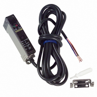
E3X-A21
Description
SENSOR PHOTO AMP USE W/E32 FIBER
Manufacturer
Omron
Type
Fiber Optic Photoelectric Sensorr
Series
E3Xr
Datasheet
1.E3X-A21.pdf
(17 pages)
Specifications of E3X-A21
Output Type
NPN
Amplifier Type
Standard
Voltage - Supply
10 V ~ 30 V
Current - Supply
35mA
Mounting Type
DIN Rail
Features
High Performance Amplifier Has Fast
Light Source
Pulse Modulated Red LED
Connection
5 Conductor Cable
Output Configuration
NPN
Sensor Output
NPN LO
Peak Reflow Compatible (260 C)
No
Sensor Housing
Rectangular
Sensor Input
Fiber Optic
Supply Voltage Max
30V
Leaded Process Compatible
No
Switch Terminals
Cable
Supply Voltage Min
10V
Rohs Compliant
No
Fiber Optic Sensor Type
Photoelectric
Lead Free Status / RoHS Status
Contains lead / RoHS compliant by exemption
Lead Free Status / RoHS Status
Contains lead / RoHS non-compliant, Contains lead / RoHS compliant by exemption
Other names
E3XA21
Z1116
Z1116


10
E3X
E3X-A
With this function, the E3X checks changes in environment
conditions (especially a change in the ambient temperature) and
self-diagnoses the resistance against the changes. The result is
shown by the indicators or an output signal.
Stable Operation Indicator
(Green Indicator)
LIGHT AXIS ADJUSTMENT WITH FLASHING FUNCTION
SELF-DIAGNOSTIC FUNCTION
1. Set the mode selector to SET.
Mode Selector
/-F
/-VG
Light Reception Indicator
(Red Indicator)
Tip of the fiber connected
to the light source side in
Self-diagnostic
Control output
(L, ON)
output*
Amount of
light
the SET mode
Indicator
OFF
OFF
ON
0.8
ON
1.2
1
10
*If the self-diagnostic output is ON when the sensing object is
moving at low speed, use the E3X with an ON-delay timer circuit.
Green
Improper Light Axis
Flashing
3. Set the mode selector to L-ON or D-ON after the
Displays
Output:
2. Adjust the light axis by moving the fiber with
Flashing
the light flashing.
light axis is adjusted.
Stable Operation Indicator: Changes in environmental
conditions (changes in the ambient temperature, the
operating voltage, or the volume of dust) are checked and
the resistance against them are self-diagnosed. The result
is shown via the indicator.
Light Reception Indicator: The amount of light received is
shown by this indicator.
The resistance against changes in environmental
conditions is shown by the indicator and the result is
output.
0.3 s min.
light ON
Green
Red
Light axis
adjusted
0.3 s min.
Proper Light Axis
Flashing
Light ON with
no flashing
Green
Operating level x 1.2
Operating level
Operating level x 0.8
E3X
Related parts for E3X-A21
Image
Part Number
Description
Manufacturer
Datasheet
Request
R

Part Number:
Description:
EXPANDABLE A/D NPN FO AMP
Manufacturer:
Omron
Datasheet:

Part Number:
Description:
EXPANDABLE A/D PNP FO AMP
Manufacturer:
Omron
Datasheet:

Part Number:
Description:
PREWIRED A/D PNP FO AMP
Manufacturer:
Omron
Datasheet:

Part Number:
Description:
PREWIRED A/D NPN FO AMP
Manufacturer:
Omron
Datasheet:

Part Number:
Description:
Industrial Photoelectric Sensors Power + input conn Master 4 cond 2M
Manufacturer:
Omron
Datasheet:
Part Number:
Description:
Industrial Photoelectric Sensors For additional amps Slave 2 cond 2M
Manufacturer:
Omron
Datasheet:

Part Number:
Description:
SENSOR PHOTOAMP FIBER 2M CBL
Manufacturer:
Omron
Datasheet:

Part Number:
Description:
SENSOR PHOTO AMP FIBEROPTC W/TMR
Manufacturer:
Omron
Datasheet:
Part Number:
Description:
RED LED NPN PREWIRE PTUNE
Manufacturer:
Omron
Datasheet:

Part Number:
Description:
G6S-2GLow Signal Relay
Manufacturer:
Omron Corporation
Datasheet:
Part Number:
Description:
Compact, Low-cost, SSR Switching 5 to 20 A
Manufacturer:
Omron Corporation
Datasheet:
Part Number:
Description:
Manufacturer:
Omron Corporation
Datasheet: