HF70ACC635050-T TDK Corporation, HF70ACC635050-T Datasheet - Page 2
HF70ACC635050-T
Manufacturer Part Number
HF70ACC635050-T
Description
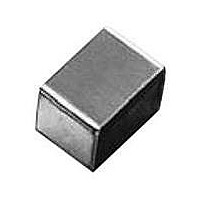
FERRITE CHIP 500 OHM 3.0A 2520
Manufacturer
TDK Corporation
Series
HF70ACCr
Datasheet
1.HF30ACC321611-T.pdf
(5 pages)
Specifications of HF70ACC635050-T
Package / Case
2520 (6350 Metric)
Impedance @ Frequency
500 Ohm @ 100MHz
Current Rating
3A
Dc Resistance (dcr)
40 mOhm Max
Filter Type
Differential Mode - Single
Number Of Lines
1
Mounting Type
Surface Mount
Shielding
Unshielded
Test Frequency
100 MHz
Product
Chip Ferrite Beads
Impedance
500 Ohms
Tolerance
25 %
Maximum Dc Current
3 Amps
Maximum Dc Resistance
0.04 Ohms
Operating Temperature Range
- 40 C to + 125 C
Termination Style
SMD/SMT
Lead Free Status / RoHS Status
Lead free / RoHS Compliant
Lead Free Status / RoHS Status
Lead free / RoHS Compliant, Lead free / RoHS Compliant
Other names
445-6189-2
Available stocks
Company
Part Number
Manufacturer
Quantity
Price
Company:

Part Number:
HF70ACC635050-T
Manufacturer:
TI
Quantity:
7 200
Part Number:
HF70ACC635050-T
Manufacturer:
TDK/东电化
Quantity:
20 000


Chip Beads(SMD)
For Power Line
HF70ACC, HF50ACC, HF30ACC Series
FEATURES
• With 4 types rated at 1.5A and 3 types rated at 3A, and with a
• Effective EMC suppression over a broad band can be achieved
• Available reflow soldering.
• It is a product conforming to RoHS directive.
PRODUCT IDENTIFICATION
(1) Material name
(2) Series name
(3) Dimension code
(4) Packaging style
TEMPERATURE RANGES
Operating
Storage
PACKAGING STYLE AND QUANTITIES
Packaging style
Taping
HANDLING AND PRECAUTIONS
• Before soldering, be sure to preheat components. The preheat-
• After mounting components onto the printed circuit board, do not
• Do not expose the inductors to stray magnetic fields.
• Avoid static electricity discharge during handling.
• When hand soldering, apply the soldering iron to the printed cir-
• Conformity to RoHS Directive: This means that, in conformity with EU Directive 2002/95/EC, lead, cadmium, mercury, hexavalent chromium, and specific
• Please contact our Sales office when your application are considered the following:
• All specifications are subject to change without notice.
HF70 ACC 201209 - T
The device’s failure or malfunction may directly endanger human life (e.g. application for automobile/aircraft/medical/nuclear power devices, etc.)
(1)
bromine-based flame retardants, PBB and PBDE, have not been used, except for exempted applications.
range of frequency characteristics available for each type, the
ACC series facilitates selection of the most appropriate part for
any given application.
simply be inserting this product into the DC power line on the cir-
cuit board.
ing temperature should be set so that the temperature difference
between the solder temperature and product temperature does
not exceed 150°C.
apply stress through board bending or mishandling.
cuit board only. Temperature of the iron tip should not exceed
350°C. Soldering time should not exceed 3 seconds.
T: ø180mm reel taping
TL: ø330mm reel taping
(2)
(3)
Type
201209
321611
322513
453215
575018
575032
635050
(4)
–40 to +125°C
–40 to +125°C
Quantity
2000 pieces/reel
2000 pieces/reel
2000 pieces/reel
1000 pieces/reel
500 pieces/reel
500 pieces/reel
300 pieces/reel
SHAPES AND DIMENSIONS/CIRCUIT DIAGRAM
Type
201209
321611
322513
453215
575018
575032
635050
• Dimension without tolerance is reference value.
RECOMMENDED PC BOARD PATTERN
REFLOW SOLDERING
Type
201209
321611
322513
453215
575018
575032
635050
a
D
L
b
L
2.0±0.2
3.2±0.2
3.2±0.2
4.5±0.25
5.7±0.4
5.7±0.4
6.4±0.4
a
1.0
1.1
1.1
1.5
2.0
2.0
2.0
a
Terminal electrode
Ferrite
Insulation resin
W
1.25±0.2
1.6±0.2
2.5±0.2
3.2±0.25
5.0±0.3
5.0±0.3
5.0±0.3
b
1.0
2.2
2.2
3.0
4.0
4.0
4.5
Resist
Land pattern
Conformity to RoHS Directive
001-02 / 20101125 / e9413_acc.fm
Dimensions in mm
T
0.9±0.2
1.1±0.2
1.3±0.2
1.5±0.25
1.8±0.3
3.2±0.3
4.74±0.3
No polarity
c
1.0
1.4
2.3
3.0
5.8
5.8
5.8
Dimensions in mm
0.2
0.2
0.2
D
0.3±0.2
0.3±0.2
0.3±0.2
0.3±0.2
(1/4)
Related parts for HF70ACC635050-T
Image
Part Number
Description
Manufacturer
Datasheet
Request
R

Part Number:
Description:
TDK DC to DC Converters, DC to AC Inverters
Manufacturer:
TDK Corporation
Datasheet:
Part Number:
Description:
TDK DC to DC Converters, DC to AC Inverters
Manufacturer:
TDK Corporation
Datasheet: