SRP7030-R20FM Bourns Inc., SRP7030-R20FM Datasheet
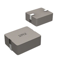
INDUCTOR POWER 0.20UH SHIELD SMD

SRP7030-R20FM

Manufacturer Part Number
SRP7030-R20FM
Description
INDUCTOR POWER 0.20UH SHIELD SMD
Manufacturer
Bourns Inc.
Series
SRP7030Fr
Type
Iron Corer
Datasheet

Specifications of SRP7030-R20FM

Inductance
200nH
Tolerance
±20%
Shielding
Shielded
Current
23A
Current - Saturation
34A
Dc Resistance (dcr)
2.4 mOhm Max
Package / Case
0.299" L x 0.256" W x 0.118" H (7.60mm x 6.50mm x 3.00mm)
Mounting Type
Surface Mount
Operating Temperature
-55°C ~ 125°C
Frequency - Test
100kHz
Material - Core
Iron
Applications
Power Supplies
Product
Shielded Power Inductors
Maximum Dc Current
23 Amps
Maximum Dc Resistance
2.4 mOhms
Dimensions
6.5 mm W x 6.5 mm L x 3 mm H
Operating Temperature Range
- 55 C to + 125 C
Termination Style
SMD/SMT
Lead Free Status / RoHS Status
Lead free / RoHS Compliant
Q @ Freq
-
Self Resonant Freq
-
Current - Temperature Rise
-
Lead Free Status / Rohs Status
Lead free / RoHS Compliant
Other names
SRP7030-R20FMTR

Available stocks

Company
Part Number
Manufacturer
Quantity
Price
Part Number:
SRP7030-R20FM
Manufacturer:
BOURNS
Quantity:
46 000
Part Number:
SRP7030-R20FM
Manufacturer:
Bourns Inc.
Quantity:
1 992
*RoHS Directive 2002/95/EC Jan 27 2003 including Annex.
Specifi cations are subject to change without notice.
Customers should verify actual device performance in their specifi c applications.
Bourns Part No.
SRP7030-R10FM
SRP7030-R15FM
SRP7030-R20FM
SRP7030-R22FM
SRP7030-R33FM
SRP7030-R47FM
SRP7030-R56FM
SRP7030-R68FM
SRP7030-R82FM
SRP7030-1R0FM
SRP7030-1R1FM
SRP7030-1R5FM
SRP7030-2R2FM
SRP7030-3R3FM
SRP7030-4R7FM
SRP7030-5R6FM
SRP7030-6R8FM
SRP7030-8R2FM
SRP7030-100FM
Electrical Specifi cations
Soldering Profi le
Electrical Schematic
275
225
175
125
75
25
0
150 °C
<1> Maximum of 10 seconds
between +255 °C and +260 °C
50
L (μH) ±20 %
Inductance
Ramp Up
4 °C/second maximum
120-150 seconds
0.10
0.15
0.20
0.22
0.33
0.47
0.56
0.68
0.82
1.0
1.1
1.5
2.2
3.3
4.7
5.6
6.8
8.2
10
100
190°C
<1> 255 °C
Time (Seconds)
220 °C
150
10 seconds minimum
I rms
4.5
4.5
3.5
(A)
32
28
23
23
18
17
15
15
12
11
11
10
SRP7030F Series - Shielded Power Inductors
Features
7
7
5
5
60 seconds
Recommended Layout
maximum
Shielded construction
Flat wire
Unit height as low as 3.0 mm
Inductance range: 0.1 to 10 μH
Rated current up to 32 A
RoHS compliant*
200
260 °C peak
I sat
5.5
(A)
60
37
34
34
25
19
17
17
14
13
13
12
11
10
7
6
5
5
250
(.335)
Ramp Down
5 °C/second
(.146)
8.5
3.7
300
(mΩ) Max.
DCR
1.99
(.098)
1.7
2.4
2.4
3.4
4.5
6.6
10
20
24
35
45
50
54
60
2.5
5
5
7
7
Applications
Test Voltage ..................................0.25 V
Test Frequency ......................... 100 KHz
Refl ow Soldering .. 230 °C; 50 sec. max.
Operating Temperature
Storage Temperature
Resistance to Soldering Heat
Core ..................................................Iron
Wire ........................... Enameled copper
Terminal ........................................Cu/Sn
Rated Current .... Ind. drops 20 % at Isat
Temperature Rise .... 40 °C at rated Irms
Packaging .....1000 pcs. per 13-inch reel
Materials
General Specifi cations
DC/DC converters
Power supplies for:
Product Dimensions
............................... -55 °C to +125 °C
.............................+260 °C for 10 sec.
• Portable communications equipment
• Laptop computers
• Camcorders, HDTV, car audio
• Video game consoles
systems
SRP7030-100FM:
SRP7030-R10FM ~ SRP7030-8R2FM:
DIMENSIONS:
(Temperature rise included)
(.039 ± .008)
(.299)
6.5 ± 0.2
7.6
2R2
MAX.
(.126)
3.2
(INCHES)
MAX.
MM
(.039 ± .008)
6.5 ± 0.2
(.063 ± .012)
(0.0 - .012)
(.047 ± .012)
0.0 - 0.3
1.6 ± 0.3
1.2 ± 0.3
(.118)
3.0
MAX.

Related parts for SRP7030-R20FM

SRP7030-R20FM Summary of contents

Page 1

... Electrical Specifi cations Inductance Bourns Part No. L (μH) ±20 % SRP7030-R10FM 0.10 SRP7030-R15FM 0.15 SRP7030-R20FM 0.20 SRP7030-R22FM 0.22 SRP7030-R33FM 0.33 SRP7030-R47FM 0.47 SRP7030-R56FM 0.56 SRP7030-R68FM 0.68 SRP7030-R82FM 0.82 SRP7030-1R0FM 1.0 SRP7030-1R1FM 1.1 SRP7030-1R5FM 1.5 SRP7030-2R2FM 2.2 SRP7030-3R3FM 3.3 SRP7030-4R7FM 4.7 SRP7030-5R6FM 5 ...

Page 2

... SRP7030F Series - Shielded Power Inductors L vs. I Charts SRP7030-R10FM 0.13 0.12 0.11 0.10 0.09 0. Bias (A) SRP7030-R20FM 0.22 0.20 0.18 0.16 0.14 0.12 0.10 0.08 0. Bias (A) SRP7030-R33FM 0.40 0.35 0.30 0.25 0.20 0.15 0. Bias (A) SRP7030-R56FM 0.60 0.55 0.50 0.45 0.40 0. Bias (A) SRP7030-R82FM 1.00 ...

Page 3

... SRP7030F Series - Shielded Power Inductors L vs. I Charts SRP7030-1R1FM 1.40 1.20 1.00 0.80 0.60 0.40 0. Bias (A) SRP7030-2R2FM 2.40 2.20 2.00 1.80 1.60 1.40 1. Bias (A) SRP7030-4R7FM 6.00 5.00 4.00 3.00 2.00 1.00 0. Bias (A) SRP7030-6R8FM 7.00 6.50 6.00 5.50 5.00 4.50 4.00 3.50 3.00 ...

Page 4

... SMD Trimming Potentiometer SRP7030F Series - Shielded Power Inductors SRP7030F Series - Shielded Power Inductors Packaging Specifi cations 2.0 ± 0.5 330.0 (.079 ± .020) (13.00) DIA. 13.5 ± 0.5 DIA. (.53 ± .020) 1.50 ± 0.1 (.059 ± .004) 0.3 ± 0.1 (.012 ± ...

Related keywords