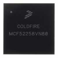
MCF52258VN80 Freescale Semiconductor, MCF52258VN80 Datasheet - Page 25

MCF52258VN80
Manufacturer Part Number
MCF52258VN80
Description
MCU 32BIT COLDFIRE V2 144MAPBGA
Manufacturer
Freescale Semiconductor
Series
MCF5225xr
Datasheet
1.MCF52256CAG66.pdf
(46 pages)
Specifications of MCF52258VN80
Core Processor
Coldfire V2
Core Size
32-Bit
Speed
80MHz
Connectivity
CAN, EBI/EMI, Ethernet, I²C, QSPI, UART/USART, USB OTG
Peripherals
DMA, LVD, POR, PWM, WDT
Number Of I /o
96
Program Memory Size
512KB (512K x 8)
Program Memory Type
FLASH
Ram Size
64K x 8
Voltage - Supply (vcc/vdd)
3 V ~ 3.6 V
Data Converters
A/D 8x12b
Oscillator Type
Internal
Operating Temperature
0°C ~ 70°C
Package / Case
144-MAPBGA
Controller Family/series
ColdFire
Ram Memory Size
64KB
No. Of Timers
2
Embedded Interface Type
CAN, Ethernet, I2C, QSPI, UART, USB
Digital Ic Case Style
MAPBGA
Rohs Compliant
Yes
Lead Free Status / RoHS Status
Lead free / RoHS Compliant
Eeprom Size
-
Available stocks
Company
Part Number
Manufacturer
Quantity
Price
Company:
Part Number:
MCF52258VN80J
Manufacturer:
Freescale Semiconductor
Quantity:
10 000
Electrical Characteristics
2.2
25
1
2
3
4
PLL @ 8 MHz
PLL @ 16 MHz
PLL @ 64 MHz
PLL @ 80 MHz
RAM standby supply current
Analog supply current
USB supply current
PLL supply current
• Normal operation: V
• Standby operation: V
• Normal operation
1
2
3
4
5
Stop mode 3 (Stop 11)
Stop mode 2 (Stop 10)
Stop mode 1 (Stop 01)
Stop mode 0 (Stop 00)
Wait / Doze
Run
Tested at room temperature with CPU polling a status register. All clocks were off except the UART and CFM (when
running from flash memory).
Peak current measured with all modules active, CPU polling a status register, and default drive strength with matching
load.
Tested using Auto Power Down (APD), which powers down the ADC between conversions; ADC running at 4 MHz in
Once Parallel mode with a sample rate of 3 kHz.
Tested with the PLL MFD set to 7 (max value). Setting the MFD to a lower value results in lower current consumption.
All values are measured with a 3.30V power supply. Tests performed at room temperature.
Refer to the Power Management chapter in the MCF52259 Reference Manual for more information on low-power
modes.
CLKOUT, PST/DDATA signals, and all peripheral clocks except UART0 and CFM off before entering low-power
mode. CLKOUT is disabled.
See the description of the Low-Power Control Register (LPCR) in the MCF52259 Reference Manual for more
information on stop modes 0–3.
Results are identical to STOP 00 for typical values because they only differ by CLKOUT power consumption.
CLKOUT is already disabled in this instance prior to entering low-power mode.
Current Consumption
Table 6. Current Consumption in Low-Power Mode, Code From Flash Memory
Mode
Characteristic
DD
DD
Table 5. Typical Active Current Consumption Specifications
4
4
4,5
5
> V
< V
STBY
SS
8 MHz (Typ)
+ 0.5 V
- 0.3 V
MCF52259 ColdFire Microcontroller, Rev. 4
21
23
9
9
16 MHz (Typ)
10
10
32
36
Symbol
I
I
DDUSB
I
DDPLL
0.150
I
STBY
I
DDA
7.0
DD
64 MHz (Typ)
15
15
56
70
Typical
(SRAM)
Active
102
22
31
84
1
2
—
—
—
—
80 MHz (Typ)
3
Typical
(Flash)
Active
17
17
65
81
100
118
30
45
1
Freescale Semiconductor
(Flash)
Unit
Peak
mA
155
185
6
36
60
20
15
1,2,3
5
2
4
2
Symbol
I
DD
Unit
mA
mA
mA
mA
A
A


