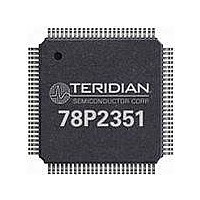
78P2351-IGT/F Maxim Integrated Products, 78P2351-IGT/F Datasheet - Page 7

78P2351-IGT/F
Manufacturer Part Number
78P2351-IGT/F
Description
LINE INTERFACE UNIT 100-LQFP
Manufacturer
Maxim Integrated Products
Specifications of 78P2351-IGT/F
Number Of Channels Per Chip
1
Propagation Delay Time
10 ns
Supply Voltage (max)
3.45 V
Supply Voltage (min)
3.15 V
Maximum Operating Temperature
+ 85 C
Package / Case
LQFP-100
Minimum Operating Temperature
- 40 C
Mounting Style
SMD/SMT
Lead Free Status / RoHS Status
Lead free / RoHS Compliant
Available stocks
Company
Part Number
Manufacturer
Quantity
Price
Company:
Part Number:
78P2351-IGT/F
Manufacturer:
VISHAY
Quantity:
14 105
Company:
Part Number:
78P2351-IGT/F
Manufacturer:
MAXIM
Quantity:
4
Company:
Part Number:
78P2351-IGT/F
Manufacturer:
Maxim Integrated
Quantity:
10 000
Design Guidelines for TERIDIAN 78P235x LIUs
SUPPLEMENTAL SURGE PROTECTION
requirements defined in the ITU K.41 and GR-1089 for indoor signal lines. Before implementing such protection
circuitry, two items should be noted:
For designs where the aforementioned protection is not enough, Teridian has verified the following circuits to
satisfy the ITU and Telcordia requirements listed above. Method 1 is a low cost protection circuit with minimal
effects on STM1e/E4 transmit pulse shapes or return loss performance.
For methods 2 (with SRV0504) and 3 (with LCO3-3.3), system vendors should make provisions to tune the return
loss characteristics according to their design.
NOTE: Surge protection diodes protect the core of the line and are not used for ESD immunity at the faceplate.
Use proper grounding techniques and system enclosures for compliance to EMI, EMC, and ESD Immunity
requirements.
Page 7 of 15
1. Teridian Semiconductor LIUs are protected against ESD (Electric Static Discharge) and rated at 2000V
2. The LIU should be isolated from the line via a transformer, which will prevent common mode spikes from
Method 1
Method 2
BNC
BNC
This section describes the recommended protection circuitry needed in order to meet the surge immunity
unless otherwise noted.
damaging the transceiver.
1
1
Figure 12: Typical Connection Diagram for Both Tx and Rx Interface
Figure 9. Single and Dual Core Transformer Diagrams (top view)
SRV0504
1
2
3
BAV99
BAV99
6
5
4
C88
DNP
2008 Teridian Semiconductor Corp.
1
3
1
3
6
5
4
6
5
4
Method 3
BNC
1
1
2
3
4
LCO3-3.3
1
2
3
4
8
7
6
5
8
7
6
5
1
3
6
5
4
Rev 2.1


