BL-33F0-0142 LIGHTING SCIENCE GROUP CORPORATION, BL-33F0-0142 Datasheet - Page 3
BL-33F0-0142
Manufacturer Part Number
BL-33F0-0142
Description
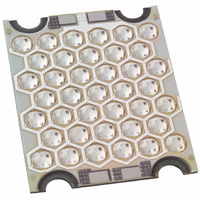
LED ARRAY RD/GN/BL 1.25X1.05"SMD
Manufacturer
LIGHTING SCIENCE GROUP CORPORATION
Datasheet
1.BL-33F0-0142.pdf
(4 pages)
Specifications of BL-33F0-0142
Color
Red, Green, Blue (RGB)
Current - Test
3 x 1.17A
Luminous Flux @ Current - Test
114lm Red, 145lm Green, 47lm Blue
Current - Max
3 x 1.17A
Lumens @ Current - Max
114lm Red, 145lm Green, 47lm Blue
Lumens/watt @ Current - Test
20lm/W Red, 17lm/W Green, 6lm/W Blue
Voltage - Forward (vf) Typ
4.8V Red, 7.2V Green, 7.2V Blue
Wavelength
624nm, 525nm, 470nm
Viewing Angle
120°
Mounting Type
Surface Mount
Package / Case
1.25" L x 1.05" W x 0.09" H (31.75mm x 26.67mm x 2.29mm)
Illumination Color
RGB
Power Consumption
5.6 W
Lead Free Status / RoHS Status
Lead free / RoHS Compliant
Lens Style/size
-
Lead Free Status / RoHS Status
Lead free / RoHS Compliant, Lead free / RoHS Compliant
Other names
521-1013


laminaceramics.com
REV.01.20.05
To see how you can realize all these design benefits, to request a sample, or to speak with an engineer
about your design, contact Lamina at 800.808.5822 or 609.265.1401 or visit www.laminaceramics.com.
Electrical Connections
Typical Beam Pattern
APPLY
APPLY
Bright Lights.
(V-)
(V-)
Bright Ideas.
VOLTAGE
VOLTAGE
GREEN
2
1
RED
TM
BLUE
APPLY
APPLY
4
3
(V-)
(V+)
VOLTAGE
VOLTAGE
H
R
Lamina LED arrays provide effi-
cient transfer of heat from the
individual LED die to a cus-
tomer supplied heat sink. All
Lamina LED arrays must be
operated at or below 125ºC. A
heat sink must be attached to
the array with sufficient cooling
capacity to keep the die junc-
tion below 125ºC. The tempera-
ture rise from the array base to
the die junction may be deter-
mined by calculating the prod-
uct of the maximum package
thermal resistance and the
desired operating power level.
The appropriate heat sink may
then be determined by:
O
R
Lamina LED arrays project a
Lambertian radiation pattern,
with projection angles built into
the package cavity at approxi-
mately 125º. It will be neces-
sary for users to create an opti-
cal reflector and lens structure
that meets their light disper-
sion requirements. Please con-
tact Lamina Application
Engineering for support with
your optical needs.
EAT
ECOMMENDATIONS
(rise)) = Operating Power (P) x
Lamina Array Thermal
PTICAL
ECOMMENDATIONS
Junction Temperature Rise (Tj
Heat Sink Thermal Resistance
Resistance (Tr)
(ºC/W) = (125 - Tj (rise) -
Maximum Ambient
Temperature)/P
S
INK
Part # BL-33F0-0142
Page 3
Related parts for BL-33F0-0142
Image
Part Number
Description
Manufacturer
Datasheet
Request
R

Part Number:
Description:
LED ARRAY RED .56 X .56 SMD
Manufacturer:
LIGHTING SCIENCE GROUP CORPORATION
Datasheet:
Part Number:
Description:
LED ARRAY AMBER .56 X .56 SMD
Manufacturer:
LIGHTING SCIENCE GROUP CORPORATION
Datasheet:

Part Number:
Description:
LED ARRAY RD/GRN/BLU .56X.56 SMD
Manufacturer:
LIGHTING SCIENCE GROUP CORPORATION
Datasheet:

Part Number:
Description:
LED ARRAY WHITE 4700K 700MA
Manufacturer:
LIGHTING SCIENCE GROUP CORPORATION
Datasheet:

Part Number:
Description:
LED ARRAY RED/GREEN/BLUE
Manufacturer:
LIGHTING SCIENCE GROUP CORPORATION
Datasheet:

Part Number:
Description:
LIGHT ENGINE ATLAS AMBER
Manufacturer:
LIGHTING SCIENCE GROUP CORPORATION

Part Number:
Description:
LIGHT ENGINE ATLAS GREEN
Manufacturer:
LIGHTING SCIENCE GROUP CORPORATION

Part Number:
Description:
LIGHT ENGINE ATLAS DAYLIGHT WHT
Manufacturer:
LIGHTING SCIENCE GROUP CORPORATION

Part Number:
Description:
LIGHT ENGINE ATLAS WARM WHITE
Manufacturer:
LIGHTING SCIENCE GROUP CORPORATION

Part Number:
Description:
LIGHT ENGINE TITAN DAYWHT 1070LM
Manufacturer:
LIGHTING SCIENCE GROUP CORPORATION
Datasheet:

Part Number:
Description:
LIGHT ENGINE TITAN RED/GRN/BLUE
Manufacturer:
LIGHTING SCIENCE GROUP CORPORATION
Datasheet:

Part Number:
Description:
LIGHT ENGINE TITAN AMBER
Manufacturer:
LIGHTING SCIENCE GROUP CORPORATION
Datasheet:

Part Number:
Description:
LIGHT ENGINE TITAN RED
Manufacturer:
LIGHTING SCIENCE GROUP CORPORATION
Datasheet:

Part Number:
Description:
LIGHT ENGINE TITAN TURBO DAY WHT
Manufacturer:
LIGHTING SCIENCE GROUP CORPORATION
Datasheet:

Part Number:
Description:
LIGHT ENGINE ATLAS RED
Manufacturer:
LIGHTING SCIENCE GROUP CORPORATION