STEVAL-CCA018V1 STMicroelectronics, STEVAL-CCA018V1 Datasheet
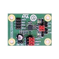
STEVAL-CCA018V1
Specifications of STEVAL-CCA018V1
Available stocks


Related parts for STEVAL-CCA018V1


STEVAL-CCA018V1 Summary of contents
Page 1
Features ■ Single 3.0 to 5.5 V supply for DAC and line driver ■ Audio line output: 2.2 Vrms for all V ■ 16- to 24-bit audio data format stereo DAC kHz sample rate ■ I²S, right- ...
Page 2
Contents Contents 1 Block diagram and pin description . . . . . . . . . . . . . . . . . . . . . . . . . . . . . 3 2 Absolute ...
Page 3
TS4657 1 Block diagram and pin description Figure 1. Block diagram Table 1. Pin description Pin name GNDD LRCLK 3 SDAT 4 BCLK 5 MCLK 6 FORMAT2 7 FORMAT1 8 STDBY 9 GNDA 10 VOUTR 11 VOUTL ...
Page 4
Block diagram and pin description Figure 2. Typical application schematics VCC 3v to 5V5 GND LRCLK J4 SDAT J3 Digital Input BCLK J2 MCLK J1 Figure 3. Typical test schematics GND LRCLK SDAT BCLK MCLK 4/26 VCCD C2 VCCA VCCD ...
Page 5
TS4657 2 Absolute maximum ratings Table 2. Key parameters and their absolute maximum ratings Symbol (1) V Supply voltage CC Digital input voltage V i MCLK, BCLK, LRCLK, SDAT, FORMAT1, FORMAT2, STDBY T Operating free air temperature range oper T ...
Page 6
Electrical characteristics 3 Electrical characteristics 3.1 Power characteristics Table 3. VCC = 3 25° C (unless otherwise specified) Symbol V Power supply CC Total supply current. Full operation 3 ...
Page 7
TS4657 3.3 DAC and output stage performances Table 3 Vcc = 5.5 V, Rload = 10 kΩ Cload = 100 pF 25° (unless otherwise specified) Symbol Operating conditions Audio data input ...
Page 8
Electrical characteristics Table Rload = 10 kΩ, Cload = 100 pF 25° C (unless otherwise specified) CC Symbol Dynamic range; A-weighted DR 16-bit data; measured at -60 dBFS, F Signal-to-noise ratio, F output ...
Page 9
TS4657 THD+N: total harmonic distortion and noise-to signal-ratio is expressed in dB given by: where VH is the rms value of the harmonic components. i SINAD: signal and noise distortion is expressed in dB. The equation is given ...
Page 10
Electrical characteristics 3.4.1 DAC digital filter response Figure 4. DAC digital filter frequency response from kHz Figure 6. DAC digital filter ripple from kHz 10/26 Figure 5. DAC digital filter transition band from 32 ...
Page 11
TS4657 3.5 Electrical measurement curves Figure 7. Crosstalk vs. frequency FS=32kHz FS=44.1kHz FS=48kHz Figure 9. Frequency response Ω 10k 0dBFS IN ° AMB Figure 11. Current consumption ...
Page 12
Electrical characteristics Figure 13. Output swing vs. power supply voltage Ω 32kHz, 44.1kHz or 48kHz F = 1kHz 0dBFS AMB Figure 15. Power supply rejection ratio vs. ...
Page 13
TS4657 Figure 19. Signal to noise ratio vs. input level Figure 20. Signal to noise ratio vs. input level Ω A-Weighted 32kHz Input Data = 18bits F = 1kHz IN ...
Page 14
Electrical characteristics Figure 25. Signal to noise ratio vs. input level Figure 26. Signal to noise ratio vs. input level Ω A-Weighted 48kHz Input Data = 18bits F = 1kHz ...
Page 15
TS4657 Figure 31. Signal to noise ratio vs. input level Figure 32. Signal to noise ratio vs. input level Ω 10k A-Weighted 32kHz Input Data = 18bits F = 1kHz IN ...
Page 16
Electrical characteristics Figure 37. Total harmonic distortion and noise vs. frequency Figure 39. Total harmonic distortion and noise vs. frequency Ω 10k 32kHz Input Data = 18bits V = -6dBFS IN ...
Page 17
TS4657 Figure 43. Total harmonic distortion and noise vs. input level Figure 45. Total harmonic distortion and noise vs. input level Figure 47. Total harmonic distortion and noise vs. input level Figure 44. Total harmonic distortion and noise V = ...
Page 18
Electrical characteristics Figure 49. Total harmonic distortion and noise vs. input level 18/ Ω 10k 48kHz Input Data = 18bits F = 1kHz IN Unweighted LPF = 20kHz ° ...
Page 19
TS4657 4 Application information 4.1 Serial audio interface 4.1.1 Master clock and data clocks Three external clock signals are applied to the TS4657. The MCLK is the external master clock applied by the audio data processor. The LRCLK is the ...
Page 20
Application information Figure 50. Audio interface formats managed by the TS4657 16-bit Right justified data format: pin FORMAT1 = VIL, FORMAT2 = VIL LRCLK SDAT BCLK 24-bit right-justified data format: pin FORMAT1 = VIH, FORMAT2 = VIL LRCLK SDAT BCLK ...
Page 21
TS4657 4.3 Recommended power-up and power-down sequences 4.3.1 Power- recommended to power-up the TS4657 prior to applying logical data in order to ensure correct ESD protection biasing. When the STDBY pin low state (VIL,) the ...
Page 22
Package information 5 Package information In order to meet environmental requirements, ST offers these devices in different grades of ® ECOPACK packages, depending on their level of environmental compliance. ECOPACK specifications, grade definitions and product status are available at: www.st.com. ...
Page 23
TS4657 ackage information 5.1 QFN20 p Figure 52. QFN20 package mechanical drawing Table 11. QFN20 package mechanical data Ref ddd Dimensions Millimeters Min. Typ. Max. 0.80 0.90 1.00 0.02 ...
Page 24
Ordering information 6 Ordering information Table 12. Order codes Order code Temperature range TS4657IQT 24/26 Package -40°C, +85°C QFN20 TS4657 Packing Marking Tape & reel K657 ...
Page 25
TS4657 7 Revision history Table 13. Document revision history Date 02-Mar-2009 Revision 1 Initial release. Revision history Changes 25/26 ...
Page 26
... Information in this document is provided solely in connection with ST products. STMicroelectronics NV and its subsidiaries (“ST”) reserve the right to make changes, corrections, modifications or improvements, to this document, and the products and services described herein at any time, without notice. All ST products are sold pursuant to ST’s terms and conditions of sale. ...