STEVAL-PCC012V1 STMicroelectronics, STEVAL-PCC012V1 Datasheet
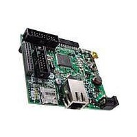
STEVAL-PCC012V1
Specifications of STEVAL-PCC012V1
Available stocks


Related parts for STEVAL-PCC012V1


STEVAL-PCC012V1 Summary of contents
Page 1
... Introduction This user manual describes the implementation of the STEVAL-PCC012V1 demonstration board. The STEVAL-PCC012V1 demonstration board is equipped with an Ethernet interface, four digital/analog extension connectors (I two different Wi-Fi modules, an OFDM PRIME power line networking extension connector and a microSD™ Card socket with SPI interface. It also features a 5-way general purpose joystick, four general purpose LEDs and two LEDs dedicated to user interface ...
Page 2
... Contents Contents 1 Introduction . . . . . . . . . . . . . . . . . . . . . . . . . . . . . . . . . . . . . . . . . . . . . . . . 1 2 STEVAL-PCC012V1 key features . . . . . . . . . . . . . . . . . . . . . . . . . . . . . . . 6 2.1 Order code . . . . . . . . . . . . . . . . . . . . . . . . . . . . . . . . . . . . . . . . . . . . . . . . . 7 3 Block diagram . . . . . . . . . . . . . . . . . . . . . . . . . . . . . . . . . . . . . . . . . . . . . . 8 4 Demonstration board layout . . . . . . . . . . . . . . . . . . . . . . . . . . . . . . . . . . . 9 5 Configuration . . . . . . . . . . . . . . . . . . . . . . . . . . . . . . . . . . . . . . . . . . . . . . 10 5.1 Ethernet . . . . . . . . . . . . . . . . . . . . . . . . . . . . . . . . . . . . . . . . . . . . . . . . . . 10 5.2 Power supply . . . . . . . . . . . . . . . . . . . . . . . . . . . . . . . . . . . . . . . . . . . . . . 11 5.3 General purpose 5-way joystick SW1 . . . . . . . . . . . . . . . . . . . . . . . . . . . . 12 5.4 LEDs . . . . . . . . . . . . . . . . . . . . . . . . . . . . . . . . . . . . . . . . . . . . . . . . . . . . 12 5.5 SPI bus communication . . . . . . . . . . . . . . . . . . . . . . . . . . . . . . . . . . . . . . USART signals branching for MEMS, Wi-Fi, digital audio and PLM ...
Page 3
UM0896 6.7 U10 Wi-Fi module-2 debugging signals TXupd and RXupd . . . . . . . . . . . 22 6.8 Ethernet RJ45 connectors CN5 . . . . . . . . . . . . . ...
Page 4
List of tables List of tables Table 1. Order code . . . . . . . . . . . . . . . . . . . . . . . . . . . . . . ...
Page 5
... UM0896 List of figures Figure 1. STEVAL-PCC012V1 . . . . . . . . . . . . . . . . . . . . . . . . . . . . . . . . . . . . . . . . . . . . . . . . . . . . . . . 1 Figure 2. STEVAL-CCA021V1 . . . . . . . . . . . . . . . . . . . . . . . . . . . . . . . . . . . . . . . . . . . . . . . . . . . . . . . 6 Figure 3. STEVAL-MKI0xxV1 . . . . . . . . . . . . . . . . . . . . . . . . . . . . . . . . . . . . . . . . . . . . . . . . . . . . . . . 7 Figure 4. Block diagram of STEVAL-PCC012V1 . . . . . . . . . . . . . . . . . . . . . . . . . . . . . . . . . . . . . . . . . 8 Figure 5. STEVAL-PCC012V1 - connector map . . . . . . . . . . . . . . . . . . . . . . . . . . . . . . . . . . . . . . . . . 9 Figure 6. SD Card formats . . . . . . . . . . . . . . . . . . . . . . . . . . . . . . . . . . . . . . . . . . . . . . . . . . . . . . . . . 15 Figure 7. JTAG connector pinout . . . . . . . . . . . . . . . . . . . . . . . . . . . . . . . . . . . . . . . . . . . . . . . . . . . . 17 2 Figure audio connector of the TS4657 audio card - schematic . . . . . . . . . . . . . . . . . . . . . . . . 17 Figure 9. Digital MEMS connector pinout . . . . . . . . . . . . . . . . . . . . . . . . . . . . . . . . . . . . . . . . . . . . . 18 Figure 10. ...
Page 6
... STEVAL-PCC012V1 key features 2 STEVAL-PCC012V1 key features ● Ethernet RJ45 connectors (ST802RT1A) ● USB-OTG with 0.5 A onboard power supply ● General purpose extension connector with GPIOs, ADC, I ● DC/DC converter L7986A (+ ● MicroSD Card™ socket ● Two positions for optional Wi-Fi modules ● ...
Page 7
... UM0896 Figure 3. STEVAL-MKI0xxV1 Refer to user manual UM0722 for details on how to use the STEVAL-CCA021V1. 2.1 Order code Table 1. Order code Part number STEVAL-PCC012V1 STEVAL-CCA021V1 STEVAL-PCC012V1 key features STM32F107xx connectivity gateway Audio demonstration board (stereo DAC, Class-D amplifier) Doc ID 17009 Rev 1 Note 7/43 ...
Page 8
... Block diagram 3 Block diagram Figure 4. Block diagram of STEVAL-PCC012V1 8/43 Doc ID 17009 Rev 1 UM0896 ...
Page 9
... UM0896 4 Demonstration board layout Figure 5. STEVAL-PCC012V1 - connector map CN1 JTAG CN8 analog digital extension JP2 Crystal switch Reset Power line network extension connector SB1 Ethernet options CN6 digital extension Optional Wi-Fi module-1 Wi-Fi module-2 CN9 CN5 microSD Ethernet optional Wi-Fi module-2 ...
Page 10
Configuration 5 Configuration 5.1 Ethernet An Ethernet PHY U5 is available on the board connected through the media independent interfaces (MII, and reduced MII, RMII) to the Ethernet MACs of the STM32™ microcontroller. If the Ethernet PHY is ...
Page 11
... RMII and pulled low for MII during reset or power-up of the PHY. 5.2 Power supply The STEVAL-PCC012V1 demonstration board is designed to be powered power supply from CN2, P2. The board is protected against overvoltage by D4 Transil™ diode (SM6T33A) and against possible reverse polarity voltage from a wrong power plug- Schottky diode (STPS3L40U) ...
Page 12
Configuration 5.3 General purpose 5-way joystick SW1 A 5-way general purpose joystick is available on the top side of the board. Table 7. Joystick direction mapping STM32 pin mapping 5.4 LEDs 4 general purpose LEDs (LD1-LD4) are available on the ...
Page 13
UM0896 2 5 USART signals branching for MEMS, Wi-Fi, digital audio and PLM Table 9. MEMS, Wi-Fi, PLM I Jumper JP2 (3-pin resistor) JP3 (3-pin resistor) Table 10. Digital audio I Jumper JP6 (3-pin resistor) JP7 (3-pin resistor) ...
Page 14
... Clock source setting Jumper JP1 (3-pin resistor) The benefit of using crystal resonator of desired frequency is described in STEVAL- CCA021V1 user manual UM0722. The correct crystal resonator frequency must be chosen with regard to using PHY or not. If the PHY is used, only X2 can be used. 5.9 Reset button A manual reset button (RESET) is available on the board top side ...
Page 15
UM0896 5.10 USB-OTG configuration The STM32 microcontroller can distinguish between the host and device mode of the connected USB circuit by reading ID pin possible to disconnect ID pin from USB connector CN4 (see Table 13. USB-OTG configuration ...
Page 16
Configuration 5.12 Wi-Fi optional modules There are two positions for optional Wi-Fi modules: Table 14. Optional Wi-Fi modules configuration Position U9 - module-1 U10 - module-2 5.12.1 Wi-Fi optional module-1 U9 settings Table 15. Wi-Fi optional module-1 U9 settings Jumper ...
Page 17
... JTAG connector pinout Table 17. JTAG connector signals Pin Signal JTRST 4 GND 5 JTDI 6.2 Audio extension connector CN3 The CN3 connector allows to connect an STEVAL-CAA021V1 audio demonstration board. 2 Figure audio connector of the TS4657 audio card - schematic Pin Signal Pin 6 GND 11 7 JTMS 12 8 GND 13 ...
Page 18
... Analog/digital MEMS extension connector CN6 and CN8 The CN6 and CN8 connectors allows to connect STEVAL-MKI0xxV1 MEMS demonstration boards (gyroscope, accelerometer) that are compatible with 24 DIL socket. The MEMS extension must be fitted in both connectors CN6 and CD8 in the same time. The MEMS extension when plugged uses only the right half of the CN8 connector terminals ...
Page 19
UM0896 Table 19. Digital MEMS connector signals Pin Figure 10. GPIO and analog connector pinout Signal (MEMS High-pass filter reset, signal for gyroscope SPI - ...
Page 20
... U9 Wi-Fi module-1 write protect (PC15 Wi-Fi module-1 chip enable (PE15) 23 Additional information can be found in the STEVAL-MK10xxV1 user manual. 6.4 Power line networking extension connector CN7 The connector CN7 is dedicated for the interconnection with ST7590 OFDM PRIME compliant power line modem demonstration board through UART and SPI. ...
Page 21
UM0896 Table 21. Connector CN7 for PLM, USART and SPI interface Pin Signals xxxx_LV mean, that these signals operate up to VCC_LV voltage level. VCC_LV is connected to 3.3 V. 6.5 Power test points These three testing ...
Page 22
Connectors 6.7 U10 Wi-Fi module-2 debugging signals TXupd and RXupd These two testing points allow to update the firmware of the optional Wi-Fi module-2. Table 24. U10 Wi-Fi module-2 debugging signals TXupd and RXupd Signal TXupd RXupd 6.8 Ethernet RJ45 ...
Page 23
UM0896 6.9 MicroSD Card connector CN9 Figure 13. MicroSD Card connector CN9 Table 26. MicroSD Card connector CN9 Pin Description NC CS_SDcard (PE7) MOSI (SPI - PA7) 1 +3.3 V SCK (SPI - PA5) 1 ...
Page 24
Connectors 6.10 Schematics Figure 14. Power supply 24/43 Doc ID 17009 Rev 1 UM0896 ...
Page 25
UM0896 Figure 15. STM32 - part 1(inputs, outputs, clock, reset) Doc ID 17009 Rev 1 Connectors 25/43 ...
Page 26
Connectors Figure 16. STM32 - part 2 (JTAG, LEDs, audio extension connector) 26/43 Doc ID 17009 Rev 1 UM0896 ...
Page 27
UM0896 Figure 17. STM32 - part 3 (joystick, analog decoupling, DAC_FMT signals) Doc ID 17009 Rev 1 Connectors 27/43 ...
Page 28
Connectors Figure 18. Ethernet - part 1 (PHY pinout) 28/43 Doc ID 17009 Rev 1 UM0896 ...
Page 29
UM0896 Figure 19. Ethernet - part 2 (overvoltage protection, PHY configuration) Doc ID 17009 Rev 1 Connectors 29/43 ...
Page 30
Connectors Figure 20. Ethernet - part 3 (magnetics) 30/43 Doc ID 17009 Rev 1 UM0896 ...
Page 31
UM0896 Figure 21. USB-OTG Doc ID 17009 Rev 1 Connectors 31/43 ...
Page 32
Connectors Figure 22. Wi-Fi module-1 32/43 Doc ID 17009 Rev 1 UM0896 ...
Page 33
UM0896 Figure 23. Wi-Fi module-2 Doc ID 17009 Rev 1 Connectors 33/43 ...
Page 34
Connectors Figure 24. MicroSD Card 34/43 Doc ID 17009 Rev 1 UM0896 ...
Page 35
UM0896 Figure 25. MEMS extension connectors Doc ID 17009 Rev 1 Connectors 35/43 ...
Page 36
Connectors 6.11 Power supply connectors CN2, P2 Figure 26. Power supply connector CN2 Table 27. Power supply connector CN2 Pin 1 2 Figure 27. Power supply connector P2 Table 28. Power supply connector P2 36/43 Signal GND ...
Page 37
... The “CG demonstration” demonstrates the audio and Ethernet capabilities of the board. It also demonstrates the MEMS sensor data acquisition feature. To run the CG demonstration properly, the STEVAL-PCC012V1 and STEVAL-CCA021V1 must be interconnected. To perform MEMS sensor data acquisition, one of the compatible STEVAL-MKI0xxV1 boards should be connected. ...
Page 38
Evaluation software Table 29. Board function indication after reset for server/clients example Function LED1 Static IP Client Server Figure 28. Connectivity Gateway Webserver demonstration 38/43 LED2 Off Off Off Off Off On Doc ID 17009 Rev 1 UM0896 LED3 LED4 ...
Page 39
UM0896 8 BOM of the board Table 30. Bill of material Designator LD1, LD3 LD2, LD5 LD4, LD6 D4 RESET SB4 D1, D2, D3, D5 CN5 R11, R14, R16, R18, R19, R20, R21, R22, R23, R48 10 kΩ R17 R2 ...
Page 40
BOM of the board Table 30. Bill of material (continued) Designator R27, R29, R31, R33, R34, R35, R36, R37, R38, R39, R40, R41, R42, R43, R44, R45, R46, R47, R49, R50, R51, R52, R53, R54, R55, R56, R57, R58, R59 ...
Page 41
UM0896 Table 30. Bill of material (continued) Designator L3, L4 RXupd, TXupd SW1 Value L5973D Doc ID 17009 Rev 1 BOM of the board Comment MLS0805-4S4-300 Update Joystick STM32F107VCT6_256K ST:L5973D STMPS2141STR USBLC6-2P6 ZG2100M 41/43 ...
Page 42
Revision history 9 Revision history Table 31. Document revision history Date 12-Mar-2010 42/43 Revision 1 Initial release. Doc ID 17009 Rev 1 UM0896 Changes ...
Page 43
... UM0896 Information in this document is provided solely in connection with ST products. STMicroelectronics NV and its subsidiaries (“ST”) reserve the right to make changes, corrections, modifications or improvements, to this document, and the products and services described herein at any time, without notice. All ST products are sold pursuant to ST’s terms and conditions of sale. ...