CP2501DK Silicon Laboratories Inc, CP2501DK Datasheet
CP2501DK
Specifications of CP2501DK


Related parts for CP2501DK

CP2501DK Summary of contents
Page 1
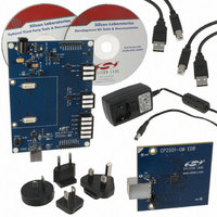
CP250 D X EVELOPMENT 1. Kit Contents The CP250x Development Kit contains the following items: CP250x Motherboard CP2501 Development Daughter Board CP250x Development Kit Quick-Start Guide Product information CD-ROM including the following: Silicon Laboratories Integrated Development ...
Page 2
CP2501-DK CP2501-GM EDB 2501 J1 VBUS VREGIN VDD 2 AC Adapter Place shorting blocks on PWR VDD_DEBUG VDD_PWR +3VD J1 J15 VPP P1 SILICON LABS www.silabs.com SILICON LABS D10 F326 www.silabs.com ...
Page 3
Software Installation The included CD-ROM contains the Silicon Labs Integrated Development Environment (IDE), 8051 evaluation toolset, optional software utilities, and additional documentation. Insert the CD-ROM into your PC’s CD-ROM drive. An installer will automatically launch, allowing you to install ...
Page 4
CP2501-DK 4.2. Silicon Labs IDE The Silicon Labs IDE integrates a source-code editor, source-level debugger and in-system programmer. The following sections discuss how to open an example project in the IDE, build the source code, and download it to the ...
Page 5
CP250x Configuration Wizard The CP250x Configuration Wizard generates the initial firmware project for CP250x devices based on the user’s system requirements. Code is generated through the use of dialog boxes as shown in Figure 2. Figure 2. CP250x Configuration ...
Page 6
CP2501-DK 5. Development Boards The CP2501 Development Kit includes a motherboard that interfaces to a daughter board. The CP2501 Development Daughter Board contains a CP2501 device to be used for preliminary software development. Numerous input/output (I/O) connections are provided on ...
Page 7
P3 J7 J15 VPP D10 F326 D11 RESET D12 P5 Figure 3. CP250x Motherboard with Default Shorting Block Positions CP2501-GM EDB P3 J1 VBUS VREGIN VDD Figure 4. CP2501 Development Daughter Board H1 PWR GPIO7-0 J3 J13 ...
Page 8
CP2501-DK 5.1. Switch and LEDs The RESET switch is connected to the RST pin of the CP250x. Pressing RESET puts the device into its hardware- reset state. Four LEDs are also provided on the motherboard. The red LED labeled “PWR” ...
Page 9
USB Debug Device (DEBUG/P5) A universal serial bus (USB) connector (P5) provides the onboard debug and programming interface. The debug/ programming MCU and associated circuitry are powered through the USB connector, which can also supply the rest of the ...
Page 10
CP2501-DK 6. Schematics 10 Rev. 0.1 ...
Page 11
Rev. 0.1 CP2501-DK 11 ...
Page 12
CP2501-DK 12 Rev. 0.1 ...
Page 13
N : OTES Rev. 0.1 CP2501-DK 13 ...
Page 14
... Should Buyer purchase or use Silicon Laboratories products for any such unintended or unauthorized ap- plication, Buyer shall indemnify and hold Silicon Laboratories harmless against all claims and damages. Silicon Laboratories and Silicon Labs are trademarks of Silicon Laboratories Inc. Other products or brandnames mentioned herein are trademarks or registered trademarks of their respective holders. ...