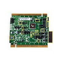
TWR-S08MM128 Freescale Semiconductor, TWR-S08MM128 Datasheet - Page 11

TWR-S08MM128
Manufacturer Part Number
TWR-S08MM128
Description
TOWER SYSTEM BOARD MC9S08MM128
Manufacturer
Freescale Semiconductor
Series
ColdFire®, Flexis™r
Type
MCUr
Datasheets
1.TWR-S08MM128.pdf
(12 pages)
2.TWR-S08MM128.pdf
(13 pages)
3.MC9S08MM128CMB.pdf
(52 pages)
Specifications of TWR-S08MM128
Contents
Board
Processor To Be Evaluated
9S08MM128
Data Bus Width
8 bit
Interface Type
USB, CAN
Silicon Manufacturer
Freescale
Core Architecture
Coldfire, HCS08
Core Sub-architecture
Coldfire V1, HCS08
Silicon Core Number
MCF51, MC9S08
Silicon Family Name
Flexis - MCF51MM, Flexis - S08MM
Rohs Compliant
Yes
For Use With/related Products
Freescale Tower System, MC9S08MM128
Lead Free Status / RoHS Status
Lead free / RoHS Compliant
6 OSBDM
An on‐board, MC9S08JM60 based OSBDM circuit provides a debug interface to the MC9S08MM128.
The MC9S08JM60 is a USB‐enabled microcontroller with an 8‐bit HC9S08 core. The OSBDM circuit
provides a USB‐to‐debug interface that allows run‐control and debugging of the MC9S08MM128 target
device. The USB drivers required to communicate with the OSBDM are provided in development tools
such as Freescale CodeWarrior. When TWR‐S08MM128 is used stand‐alone, this single USB
connection can also be used for power.
6.1
The MC9S08JM60 device used in the OSBDM circuit is preprogrammed with OSBDM debugger
firmware and a USB Bootloader. The bootloader mode can be used to update the OSBDM debugger
firmware if an update becomes available. Jumper J12 determines which application will run following a
power‐on reset. If the Bootloader Mode is chosen (jumper shunt on J12), the bootloader will be
executed, allowing in‐circuit reprogramming of the JM60 flash memory via USB. Refer to Application
Note AN3561 on the Freescale website (http://www.freescale.com) for details on the USB Bootloader.
The USB Bootloader communicates with a GUI application running on a host PC. The GUI application
can be found on the Freescale website; search keyword “JM60 GUI.” Refer to section 2.5 and 3.3 of
AN3561 for details on installing and running the application.
7 Bootloader Mode For MC9S08MM128
Unlike MC9S08JM60, MC9S08MM128 has an on‐chip ROM based USB bootloader that allows the
MC9S08MM128 for mass erase and programming via its USB interface. This on‐chip bootloader does
not consume user flash space. To enable USB bootloader mode for MC9S08MM128, on the TWR‐
S08MM128 module, set SW3 DIP switch 2 and 3 to position 3, as indicated in Figure 7. NOTE: Under
normal development you will need to set SW3 DIP switch 2 and 3 to position 2.
Bootloader Mode For MC9S08JM60
Mode to a host USB port. Otherwise, the JM60 USB device will not be recognized and
The JM60 GUI Installer should be run before connecting the OSBDM in Bootloader
the proper drivers will not be loaded.
TWR‐MC9S08MM128 User Manual
Note:
Page 11 of 13


