USB-RS232-PCBA FTDI, Future Technology Devices International Ltd, USB-RS232-PCBA Datasheet - Page 10
USB-RS232-PCBA
Manufacturer Part Number
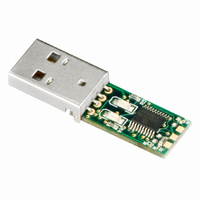
USB-RS232-PCBA
Description
MODULE USB - RS232
Manufacturer
FTDI, Future Technology Devices International Ltd
Series
USBmadeEZ-UARTr
Datasheet
1.USB-RS232-PCBA.pdf
(16 pages)
Specifications of USB-RS232-PCBA
Convert From (adapter End)
USB-A Male
Convert To (adapter End)
PCB
Features
USB to RS232 Adapter PCB Assy w/ Embedded Controller and LEDs, 1MBaud
For Use With/related Products
Windows® 2000 or higher, Linux, Max OS X
Lead Free Status / RoHS Status
Lead free / RoHS Compliant
Other names
768-1066


4.1
Table 4.1 USB-RS232-PCB Signal Descriptions
4.2
Selection of whether the POWER signal is GND, +3.3V or +5V is done using resistors. The following table
gives details of what resistors are required for the different voltage levels.
Resistor
Table 4.2 UART Signal Level Selection
Fitted
Fitted
Fitted
POWER
Name
CTS#
RTS#
Not
Not
R2
GND
TXD
RXD
USB-RS232-PCB Signal Descriptions
USB-RS232-PCB +5V/+3.3V Selection
Resistor
Fitted
Fitted
Fitted
Not
Not
R3
Output
Output
Output
Input
Input
Type
GND
Copyright © 2011 Future Technology Devices International Limited
Description
VCC floats
POWER Signal is +3.3V
POWER Signal is +5.0V
Description
Device ground supply pin.
Clear to Send Control input / Handshake signal.
Power output. Default is GND, but can be customised to
output +3.3V or +5V. If required, contact FTDI Sales Team
(sales1@ftdichip.com)
Transmit Asynchronous Data output.
Receive Asynchronous Data input.
Request To Send Control Output / Handshake signal.
USB TO RS232 UART SERIAL CONVERTER
Document Reference No.: FT_000079
PCB
Clearance No.: FTDI# 52
Datasheet Version 1.41
9
Related parts for USB-RS232-PCBA
Image
Part Number
Description
Manufacturer
Datasheet
Request
R

Part Number:
Description:
MODULE USB - RS232 WITH CABLE
Manufacturer:
FTDI, Future Technology Devices International Ltd
Datasheet:
Part Number:
Description:
CABLE USB RS232 3.3V WIRE 1.8M
Manufacturer:
FTDI, Future Technology Devices International Ltd
Datasheet:

Part Number:
Description:
CABLE USB RS232 3.3V WIRE END 5M
Manufacturer:
FTDI, Future Technology Devices International Ltd
Datasheet:

Part Number:
Description:
CABLE USB RS232 WIRE END 5M
Manufacturer:
FTDI, Future Technology Devices International Ltd
Datasheet:

Part Number:
Description:
CABLE USB RS232 5V WIRE END 5M
Manufacturer:
FTDI, Future Technology Devices International Ltd
Datasheet:

Part Number:
Description:
MODULE USB TO RS232 CONV SGL
Manufacturer:
FTDI, Future Technology Devices International Ltd
Datasheet:

Part Number:
Description:
MODULE USB TO RS232 CONV DUAL HS
Manufacturer:
FTDI, Future Technology Devices International Ltd
Datasheet:

Part Number:
Description:
MODULE USB TO RS232 CONV QUAD HS
Manufacturer:
FTDI, Future Technology Devices International Ltd
Datasheet:
Part Number:
Description:
CABLE USB RS232 10CM
Manufacturer:
FTDI, Future Technology Devices International Ltd
Datasheet:
Part Number:
Description:
CABLE USB RS232 1M DB9
Manufacturer:
FTDI, Future Technology Devices International Ltd
Datasheet:

Part Number:
Description:
IC USB TO SERIAL UART 32-QFN
Manufacturer:
FTDI, Future Technology Devices International Ltd

Part Number:
Description:
IC USB HOST CTLR VINCULUM 48LQFP
Manufacturer:
FTDI, Future Technology Devices International Ltd
Datasheet:

Part Number:
Description:
IC USB HOST VINCULUM-II 32QFN
Manufacturer:
FTDI, Future Technology Devices International Ltd
Datasheet:
Part Number:
Description:
IC USB HOST VINCULUM-II 32LQFN
Manufacturer:
FTDI, Future Technology Devices International Ltd
Datasheet:
Part Number:
Description:
IC USB HOST VINCULUM-II 48QFN
Manufacturer:
FTDI, Future Technology Devices International Ltd
Datasheet: