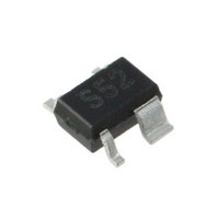
SKY65052-372LF Skyworks Solutions Inc, SKY65052-372LF Datasheet - Page 4

SKY65052-372LF
Manufacturer Part Number
SKY65052-372LF
Description
IC AMP LO-NOISE 0.4-6GHZ SC70-4
Manufacturer
Skyworks Solutions Inc
Datasheet
1.SKY65052-372LF.pdf
(9 pages)
Specifications of SKY65052-372LF
Current - Supply
100mA
Frequency
400MHz ~ 6GHz
Gain
15dB
Noise Figure
0.6dB
P1db
10dBm
Package / Case
SC-70-4, SC-82-4, SOT-323-4, SOT-343
Rf Type
Cellular
Test Frequency
2.4GHz
Voltage - Supply
2 V ~ 6 V
Lead Free Status / RoHS Status
Lead free / RoHS Compliant
Other names
863-1069-2
PRELIMINARY DATA SHEET • SKY65052-372LF LOW NOISE TRANSISTOR
Evaluation Board Description
The SKY65052-372LF Evaluation Board is used to test the
performance of the SKY65052-372LF low noise transistor. An
assembly drawing for the Evaluation Board is shown in Figure 8.
The Evaluation Board schematic diagram is shown in Figure 9.
Table 5 provides the Bill of Materials (BOM) list for Evaluation
Board components.
Circuit Design Considerations
Input and output traces have been minimized to reduce losses. All
surface mount components are 0402-sized to reduce component
parasitics. Use of 0603 or larger components is not
recommended. Component spacing has also been minimized. The
board is provisioned with two RF connectors and a DC launch. RF
connector and board loss up to component C1 is approximately
0.1 dB at 2.4 GHz.
4
Figure 7. Noise Figure vs Frequency, Input RF Connector and
Figure 5. Reverse Isolation vs Frequency Over Temperature
–10.0
–20.0
1.00
0.95
0.90
0.85
0.80
0.75
0.70
–30
–40
–50
0
1800
2000
Board Trace De-Embedded From Measurement
June 2, 2009 • Skyworks Proprietary and Confidential information • Products and Product Information are Subject to Change Without Notice • 201088A
Skyworks Solutions, Inc. • Phone [781] 376-3000 • Fax [781] 376-3100 • sales@skyworksinc.com • www.skyworksinc.com
2200
2000
(P
IN
Frequency (MHz)
Frequency (MHz)
= –20 dBm)
2400
2200
2600
2400
2800
2600
3000
Board material is 10 mil VT47 FR4 with 1 oz. copper cladding.
The RF traces are 50 Ω.
Evaluation Board Test Procedure
Step 1: Connect RF test equipment to amplifier input/output SMA
Step 2: Connect DC ground.
Step 3: Connect VDD to a +5 V supply with a current limit of
Step 4: Apply RF signal or noise source.
Figure 6. Output Return Loss vs Frequency Over Temperature
–10
–14
–18
+2
–2
–6
2000
connectors.
100 mA. Verify that the board draws approximately
55 mA.
2200
(P
IN
Frequency (MHz)
2400
= –20 dBm)
2600
2800
3000


