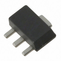
SKY65038-70LF Skyworks Solutions Inc, SKY65038-70LF Datasheet - Page 5

SKY65038-70LF
Manufacturer Part Number
SKY65038-70LF
Description
IC AMP GP LN 250M-6GHZ SOT-89
Manufacturer
Skyworks Solutions Inc
Datasheet
1.SKY65038-70LF.pdf
(14 pages)
Specifications of SKY65038-70LF
Current - Supply
140mA
Frequency
250MHz ~ 6GHz
Gain
15dB
Noise Figure
2dB
P1db
21.5dBm
Package / Case
SOT-89
Rf Type
WiMax, WLAN
Test Frequency
1GHz
Voltage - Supply
5V
Lead Free Status / RoHS Status
Lead free / RoHS Compliant
Other names
863-1065-2
Available stocks
Company
Part Number
Manufacturer
Quantity
Price
Part Number:
SKY65038-70LF
Manufacturer:
SKYWORKS/思佳讯
Quantity:
20 000
Evaluation Board Description
The Skyworks SKY65038-70LF Evaluation Board is used to test
the performance of the SKY65038-70LF LNA. An assembly
drawing for the Evaluation Board is shown in Figure 10.
Instead of using external surface mount components to test the
Evaluation Board, broadband bias Ts were used to highlight the
performance of the device, itself. Evaluation Boards are available
for 250 MHz, 900 MHz, 1900 MHz, and 2100 MHz. Typical
reference schematic diagrams are provided in Figures 11
(250 MHz), 13 (900 MHz), 15 (1900 MHz), and 17 (2100 MHz).
These are relatively wideband circuits that are useful for many
applications.
The following Tables describe the S-parameter performance and
provide the Bill of Materials (BOMs) for the four available
Evaluation Boards:
250 MHz: Tables 5 and 6.
900 MHz: Tables 7 and 8.
1900 MHz: Tables 9 and 10.
2100 MHz: Tables 11 and 12.
Table 13 provides scattering parameters for 250 MHz up to
6000 MHz, calibrated to package leads.
Biasing
The voltage supply (VDD) should be applied to the RF_OUT pin
through inductor L2. Decoupling capacitors C3 and C4 should be
placed closely to L2.
If a bias level lower than +5 V is used, the feedback resistor R1 is
required. Use the following equation to determine the value of R1
(do not install R1 for +5 V operation):
Circuit Design Configurations
The following design considerations are general in nature and
must be followed regardless of final use or configuration.
1. External components should be placed close to the package
2. Care should be taken to ensure that all RF traces are 50 Ω.
3. Paths to ground should be made as short as possible.
4. The ground pad of the SKY65038-70LF LNA has special
pins to reduce parasitics.
electrical and thermal grounding requirements. This pad is the
main thermal conduit for heat dissipation. Since the circuit
board acts as the heat sink, it must shunt as much heat as
possible from the amplifier. As such, design the connection to
R
Skyworks Solutions, Inc. • Phone [781] 376-3000 • Fax [781] 376-3100 • sales@skyworksinc.com • www.skyworksinc.com
1
200794C • Skyworks Proprietary Information • Products and Product Information are Subject to Change Without Notice • November 9, 2009
30
10
3
VDD
VDD
. 0
5
37
(1)
5. All surface mount components are 0402-sized to reduce
The different Evaluation Boards for the SKY65038-70LF are
provisioned with two RF connectors and a DC launch. All boards
have space for additional RF matching components. Unused
series locations should be populated with 0 Ω resistors or strip
lines. Unused shunt locations should be left unpopulated.
Components in the feedback path from the RF input to the DC
header should only be used if operating at less than +5 V.
Testing Procedure
Use the following procedure to set up the SKY65038-70LF
Evaluation Board for testing:
1. Connect RF test equipment to the input/output SMA
2. Connect DC ground.
3. Connect VDD to a +5 V supply with a current of 200 mA.
4. Apply an RF signal or noise source.
Package Dimensions
Typical case markings for the SKY65038-70LF are shown in
Figure 19. The PCB layout footprint is shown in Figure 20.
Package dimensions for the 4-pin SOT-89 are provided in
Figure 21, and tape and reel dimensions are shown in Figure 22.
Package and Handling Information
Instructions on the shipping container label regarding exposure to
moisture after the container seal is broken must be followed.
Otherwise, problems related to moisture absorption may occur
when the part is subjected to high temperature during solder
assembly.
The SKY65038-70LF is rated to Moisture Sensitivity Level 1
(MSL1) at 260 C. It can be used for lead or lead-free soldering.
Care must be taken when attaching this product, whether it is
done manually or in a production solder reflow environment.
Production quantities of this product are shipped in a standard
tape and reel format. For packaging details, refer to the Skyworks
Application Note Tape and Reel, document number 101568.
connectors.
Verify that the board draws approximately 150 mA.
the ground pad to dissipate the maximum wattage produced
to the circuit board. Multiple vias to the grounding layer are
required.
component parasitics. Use of 0603 or larger components is
not recommended.
DATA SHEET • SKY65038-70LF LNA
5


