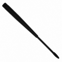
0600-00027 Laird Technologies, 0600-00027 Datasheet - Page 26

0600-00027
Manufacturer Part Number
0600-00027
Description
ANTENNA 915MHZ 1/2WV 7" RPSMA
Manufacturer
Laird Technologies
Specifications of 0600-00027
Antenna Type
Whip: 1/2 Wave, Swivel, Tilt (Right Angle)
Number Of Bands
1
Frequency
902MHz ~ 928MHz
Vswr
2
Gain
2dBi
Termination
RP-SMA
Mounting Type
Connector
Height (max)
8.25" (209.5mm)
Impedance
50 Ohms
Technology Type
1/2 Wave Wireless Transceiver Antenna
Termination Style
RPSMA
Lead Free Status / RoHS Status
Lead free / RoHS Compliant
Lead Free Status / RoHS Status
Lead free / RoHS Compliant, Lead free / RoHS Compliant
Write API Control
The OEM Host issues this command to the transceiver
to write the API Control byte.
Command: 0xCC 0x17
Number of bytes returned: 2
Response: 0xCC API Control
Set Max Power
The OEM Host Issues this command to limit the
maximum transmit power emitted by the transceiver.
This can be useful to minimize current consumption
and satisfy certain regulatory requirements. The radios
are shipped at maximum allowable power.
Command: 0xCC 0x25 New_Max_Power
Number of bytes returned: 2
Response: CCh New_Max_Power
Read Temperature
The OEM Host issues this command to read the
onboard temperature sensor. The transceiver reports
the temperature in °C where 0 – 80h corresponds to 0 –
80°C and where D8h – 0h corresponds to -40 – 0°C.
Command: 0xCC 0xA4
Number of bytes returned: 2
Response: 0xCC Temperature
Parameter Range:
Temperature = 0xD8 – 0x80
Read Digital Inputs
The OEM Host issues this command to read the state
of both digital input lines.
Command: 0xCC 0x20
Number of bytes returned: 2
Response: 0xCC Data1
Parameter Range:
Data1 = bit-0 – GI0, bit-1– GI1, bits 2 – 7: 0
Read Radio Table
The OEM Host issues this command to read the Radio
Table that resides on the transceiver. The Radio Table
stores information for up to the last 8 transceivers that
sent it a packet. This information is very useful for
providing alternative data paths.
Command: 0xCC 0x18
Response:
Byte 1 = 0xCC
Byte 2 = # of transceivers in this table (0x00-0x08)
Byte 3 = Mac (2,1,0) of transceiver #1
Byte 4 = RSSI
Byte 5 = RSSI*
Byte 6 = Stale Count of transceiver #1
Byte 7 = Mac (2,1,0) of transceiver #2
Byte 8 = RSSI
Byte 9 = RSSI*
Byte 9…n = Stale Count of transceiver #2…and so on.
Stale Count: The Stale
Count Reload (0x4F)
determines the amount
of time a radio will stay
active in the Radio
Table. The Stale Count
(min:
depends
EEPROM Setting) for a
radio is set to 0 when a
packet is received; it
then gets incremented
by one every 100ms.
When the Stale Count
of a radio reaches the
Stale
(0x4F)
considered Stale.
Radio Table can hold
up to a maximum of 8
radios’
however if the Radio
Table is full and 9th
radio is received, the
first radio that is Stale
is replaced with the
new radio. If none of
the radios are stale,
the oldest radio in the
table is replaced with
the new radio.
The RSSI is how strong the remote transceiver heard
the local transceiver, RSSI* is how strong the local
transceiver heard the remote transceiver. The table
above can be used to convert the RSSI to the
corresponding signal strength. One dBm is equal to
approximately four steps.
Note: Notice the trend between 4dBm and -12dBm
does not follow the curve.
Count
the
0x00,
Quick Tip:
information;
on
radio
Reload
max:
the
is
A
-36 to -22
-42 to -39
Strength
-12 to -6
Signal
-2 to 1
(dBm)
-46
-49
-52
-56
-59
-62
-66
-69
-72
-76
-79
-82
-86
-89
-92
4
This is because RSSI
RSSI Value
0xBD
(hex)
0x0D
0x0C
0x0C
0x0D
0x1C
0xAD
0x0E
0x0B
0x0E
0x11
0x17
0x2B
0x40
0x55
0x62
0x71
0x78
0x84
0x9A
26


