0600-00030 Laird Technologies, 0600-00030 Datasheet - Page 16
0600-00030
Manufacturer Part Number
0600-00030
Description
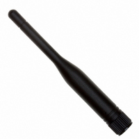
ANTENNA 915MHZ 1/4WAVE 3.5"RPSMA
Manufacturer
Laird Technologies
Specifications of 0600-00030
Antenna Type
Whip: 1/4 Wave, Fixed
Number Of Bands
1
Frequency
902MHz ~ 928MHz
Vswr
2
Gain
1dBi
Termination
RP-SMA
Mounting Type
Connector
Height (max)
3.5" (88mm)
Dimensions
3.5 in L
Technology Type
1/4 Wave Wireless Transceiver Antenna
Termination Style
RPSMA
Lead Free Status / RoHS Status
Lead free / RoHS Compliant
Lead Free Status / RoHS Status
Lead free / RoHS Compliant, Lead free / RoHS Compliant


Session_Guest_RF_Transmit
Note: All transceivers on the same network must have the same setting for Full Duplex.
I
Interface Timeout (EEPROM address 0x58), in conjunction with RF Packet Size (EEPROM address 0x5B), determines when a buffer
of data will be sent out over the RF as a complete RF packet, based on whichever condition occurs first.
Interface Timeout – Interface Timeout specifies a maximum byte gap between consecutive bytes. When that byte gap is exceeded,
the bytes in the transmit buffer are sent out over the RF as a complete packet. Interface Timeout is adjustable in 0.5ms increments
and has a tolerance of ±0.5ms. The default value for Interface Timeout is 0x04 (2ms).
RF Packet Size – When the number of bytes in the transceiver transmit buffer equals RF Packet Size, those bytes are sent out as a
complete RF packet. It is much more efficient to send a few large packets rather than many short packets as each packet sent over
the RF contains extra header bytes which are not included in the RF Packet Size. RF packet size can be set to a maximum of 0x80.
S
Care should be taken when selecting transceiver architecture, as it can have serious effects on data rates, latency, and overall
system throughput. The importance of these three characteristics will vary from system to system and should be a strong
consideration when designing the system.
M
When operating as shown in the Table 7,
an AC4790 transceiver is capable of
achieving the listed throughput.
However, in the presence of interference
or at longer ranges, the transceiver may
not be able to meet the specified
throughput.
NTERFACE
Session_Host_RF_Transmit
YSTEM
AXIMUM
IN HIGH-DENSITY APPLICATIONS, WHAT AMOUNT OF LATENCY SHOULD BE EXPECTED?
It is not easy to predict the exact amount of latency in high-density applications. There are many variables that affect
system latency. The three variables that most affect the latency are the network load, the distance between transceivers,
and whether the transceivers are operating in a broadcast or addressed mode. There is no fixed answer as to how much
latency will be introduced in the system when considering high-density applications. In these cases we can just offer
qualitative analysis of the latency in high-density applications. As the network load increases, then the number of collisions
that will occur increases. As the number of collisions increase, then the system latency increases. As the distance between
the transceivers increases, so to does the system latency. Finally, when transceivers operate in addressed mode they will
retry sending a packet up to the number of time specified in the transmit retry parameter specified in the EEPROM. As the
number of retries increases, the system latency will increase also.
Quick Tip:
T
IMING AND
O
Hop_Frame
T
VERALL
IMEOUT
S
/RF P
L
YSTEM
ATENCY
1 1
ACKET
T
HROUGHPUT
Radio not in continuous Session
Radio continuously in Session
RF_Transmit
S
IZE
2
Table 7 - Maximum Overall System Throughput
RF Status
RF_Transmit
3
Throughput (bps)
Half Duplex
RF_Transmit
25k
45k
4
Throughput (bps) each way
Full Duplex
12.5k
22.5k
16
Related parts for 0600-00030
Image
Part Number
Description
Manufacturer
Datasheet
Request
R

Part Number:
Description:
CIRCUIT PIN PRINTED .250"
Manufacturer:
Mill-Max Manufacturing Corp.
Datasheet:
Part Number:
Description:
CIRCUIT PIN PRINTED .250"
Manufacturer:
Mill-Max Manufacturing Corp.
Datasheet:
Part Number:
Description:
CIRCUIT PIN PRINTED .250"
Manufacturer:
Mill-Max Manufacturing Corp.
Datasheet:
Part Number:
Description:
CIRCUIT PIN PRINTED .250"
Manufacturer:
Mill-Max Manufacturing Corp.
Datasheet:

Part Number:
Description:
ANT 2.4GHZ 1/2 WAVE 5" RA U.FL
Manufacturer:
Laird Technologies

Part Number:
Description:
ANTENNA 2.45GHZ 7" RA U.FL PLUG
Manufacturer:
Laird Technologies

Part Number:
Description:
ANTENNA 915MHZ 1/2WV 6" RA RPSMA
Manufacturer:
Laird Technologies
Datasheet:

Part Number:
Description:
ANTENNA 2.4GHZ 5/8WV RA 7" RPSMA
Manufacturer:
Laird Technologies

Part Number:
Description:
ANTENNA 915MHZ 1/2WV 7" RA RPSMA
Manufacturer:
Laird Technologies
Datasheet:

Part Number:
Description:
ANTENNA 915MHZ 1/2WAVE 7"RA MMCX
Manufacturer:
Laird Technologies
Datasheet:

Part Number:
Description:
BLUETOOTH EVAL BOARD BTM511
Manufacturer:
Laird Technologies
Datasheet:

Part Number:
Description:
Bluetooth / 802.15.1 Modules & Development Tools BLUETTH Multimed MODLE, No ANT DEVKIT
Manufacturer:
Laird Technologies
Datasheet:

Part Number:
Description:
Bluetooth Serial Module Development Kit
Manufacturer:
Laird Technologies