0600-00029 Laird Technologies, 0600-00029 Datasheet - Page 20
0600-00029
Manufacturer Part Number
0600-00029
Description
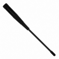
ANTENNA 915MHZ 1/2WAVE 6" RPSMA
Manufacturer
Laird Technologies
Specifications of 0600-00029
Antenna Type
Whip: 1/2 Wave, Fixed
Number Of Bands
1
Frequency
902MHz ~ 928MHz
Vswr
2
Gain
2.5dBi
Termination
RP-SMA
Mounting Type
Connector
Height (max)
6.8" (173.5mm)
Dimensions
6 in L
Technology Type
1/2 Wave Wireless Transceiver Antenna
Termination Style
RPSMA
Lead Free Status / RoHS Status
Lead free / RoHS Compliant
Lead Free Status / RoHS Status
Lead free / RoHS Compliant, Lead free / RoHS Compliant


Hardware Interface
Below is a description of all hardware pins used to control the AC4790.
GIn (Generic Inputs 0 and 1) (pins 4
and 14 respectively) and GOn
(Generic Outputs 0 and 1) (pins 1
and 9 respectively)
Both GIn pins serve as generic input pins. When
Protocol Status (byte C2h of EEPROM) is disabled,
GO0 & GO1 serve as generic outputs. When Protocol
Status is enabled, pins GO0 and GO1 serve as the
Session Status and Receive Acknowledge Status pins,
respectively. Reading and writing of these pins can be
performed using CC Commands (details can be found
in the
Hardware Protocol Status
When the GO0 pin is configured as the Session Status
pin, GO0 is normally Low. GO0 will go High when a
Session is initiated and remain High until the end of the
Session.
Receive Acknowledge Status pin, GO1 is normally Low
and will go High upon receiving a valid RF
Acknowledgement and remain High until the end
(rising edge) of the next hop.
TXD (Transmit Data) and RXD
(Receive Data) (pins 2 and 3
respectively)
Serial TTL
The AC4790-200 accepts 3.3 or 5VDC TTL level
asynchronous serial data on the RXD pin and interprets
that data as either Command Data or Transmit Data.
Data is sent from the transceiver, at 3.3V levels, to the
OEM Host via the TXD pin.
transceiver ONLY accepts 3.3V level signals.
RS-485
When equipped with an onboard RS-485 interface chip,
TXD and RXD become the half duplex RS-485 pins.
The transceiver interface will be in Receive Mode
except when it has data to send to the OEM Host. TXD
is the non-inverted representation of the data (RS485A)
and RXD is a mirror image of TXD (RS485B).
transceiver will still use RTS (if enabled).
CTS Handshaking (pin 7)
The AC4790 has an interface buffer size of 256 bytes. If
the buffer fills up and more bytes are sent to the
On-the-Fly Control Command Reference
When the GO1 pin is configured as the
The AC4790-1000
).
The
transceiver before the buffer can be emptied, data loss
will occur.
asserting CTS High as the buffer fills up and taking CTS
Low as the buffer is emptied. CTS On and CTS Off
control the operation of CTS. CTS On specifies the
amount of bytes that must be in the buffer for CTS to
be disabled (logic High). Even while CTS is disabled,
the OEM Host can still send data to the transceiver, but
it should do so carefully. Once CTS is disabled, it will
remain disabled until the buffer is reduced to the size
specified by CTS Off.
Note: The CTS On/Off bytes of the EEPROM can be set
to 1, in which case CTS will go high as data is sent in
and low when buffer is empty.
RTS Handshaking (pin 8)
With RTS disabled, the transceiver will send any
received data to the OEM Host as soon as it is
received. However, some OEM Hosts are not able to
accept data from the transceiver all of the time. With
RTS enabled, the OEM Host can prevent the
transceiver from sending it data by disabling RTS (logic
High).
transceiver can send packets to the OEM Host as they
are received.
Note: Leaving RTS disabled for too long can cause
data loss once the transceiver’s 256 byte receive buffer
fills up.
Test (pin 12)
When pulled logic Low before applying power or
resetting, the transceiver’s serial interface is forced to a
9600, 8-N-1 (8 data bits, No parity, 1 stop bit). To exit,
the transceiver must be reset or power-cycled with Test
pin logic High.
This pin is used to recover transceivers from
unknown baud rates only and should not be used
during normal operation. If the desired baud rate
is 9600, the transceiver’s Serial Interface Baud
Rate should be programmed to 9600 baud.
Quick Tip:
Once RTS is enabled (logic Low), the
The transceiver prevents this loss by
20
Related parts for 0600-00029
Image
Part Number
Description
Manufacturer
Datasheet
Request
R

Part Number:
Description:
CIRCUIT PIN PRINTED .250"
Manufacturer:
Mill-Max Manufacturing Corp.
Datasheet:
Part Number:
Description:
CIRCUIT PIN PRINTED .250"
Manufacturer:
Mill-Max Manufacturing Corp.
Datasheet:
Part Number:
Description:
CIRCUIT PIN PRINTED .250"
Manufacturer:
Mill-Max Manufacturing Corp.
Datasheet:
Part Number:
Description:
CIRCUIT PIN PRINTED .250"
Manufacturer:
Mill-Max Manufacturing Corp.
Datasheet:

Part Number:
Description:
ANT 2.4GHZ 1/2 WAVE 5" RA U.FL
Manufacturer:
Laird Technologies

Part Number:
Description:
ANTENNA 2.45GHZ 7" RA U.FL PLUG
Manufacturer:
Laird Technologies

Part Number:
Description:
ANTENNA 915MHZ 1/2WV 6" RA RPSMA
Manufacturer:
Laird Technologies
Datasheet:

Part Number:
Description:
ANTENNA 2.4GHZ 5/8WV RA 7" RPSMA
Manufacturer:
Laird Technologies

Part Number:
Description:
ANTENNA 915MHZ 1/2WV 7" RA RPSMA
Manufacturer:
Laird Technologies
Datasheet:

Part Number:
Description:
ANTENNA 915MHZ 1/2WAVE 7"RA MMCX
Manufacturer:
Laird Technologies
Datasheet:

Part Number:
Description:
BLUETOOTH EVAL BOARD BTM511
Manufacturer:
Laird Technologies
Datasheet:

Part Number:
Description:
Bluetooth / 802.15.1 Modules & Development Tools BLUETTH Multimed MODLE, No ANT DEVKIT
Manufacturer:
Laird Technologies
Datasheet:

Part Number:
Description:
Bluetooth Serial Module Development Kit
Manufacturer:
Laird Technologies