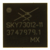
SKY73012-11 Skyworks Solutions Inc, SKY73012-11 Datasheet - Page 16

SKY73012-11
Manufacturer Part Number
SKY73012-11
Description
IC QUADRATURE DEMOD 32-RFLGA
Manufacturer
Skyworks Solutions Inc
Datasheet
1.SKY73012-11.pdf
(25 pages)
Specifications of SKY73012-11
Function
Demodulator
Lo Frequency
400MHz ~ 3.9GHz
Rf Frequency
400MHz ~ 3.9GHz
P1db
12.5dBm
Gain
-0.5dB
Noise Figure
19dB
Current - Supply
75mA
Voltage - Supply
2.7 V ~ 3.6 V
Package / Case
32-RFLGA™
Lead Free Status / RoHS Status
Lead free / RoHS Compliant
Other names
863-1082-2
Available stocks
Company
Part Number
Manufacturer
Quantity
Price
Company:
Part Number:
SKY73012-11
Manufacturer:
LT
Quantity:
19 820
DATA SHEET • SKY73012 DEMODULATOR
Evaluation Board Description
The SKY73012 Evaluation Board is used to test the performance
of the SKY73012 direct quadrature demodulator. There are three
Evaluation Boards for this device, each configured for a specific
frequency range. Each of these boards is described by the
following Figures and Tables:
• 800 to 1000 MHz: Figure 60 (schematic), Table 5 (component
• 1800 to 3900 MHz: Figure 62 (schematic), Table 6 (component
• Custom Frequency: Figure 64 (schematic), Table 7 (component
Circuit Design Considerations
The following design considerations are general in nature and
must be followed regardless of final use or configuration.
1. Paths to ground should be made as short as possible.
2. The ground pad of the SKY73012 direct quadrature
3. Two external output bypass capacitors are required on the
16
values), and Figure 61 (assembly diagram)
values), and Figure 63 (assembly diagram)
values), and Figure 65 (assembly diagram)
demodulator has special electrical and thermal grounding
requirements. This pad is the main thermal conduit for heat
dissipation. Since the circuit board acts as the heat sink, it
must shunt as much heat as possible from the device. As
such, design the connection to the ground pad to dissipate the
maximum wattage produced to the circuit board.
VCC pin. The values of these capacitors will change with
respect to the desired RF frequency. One capacitor should be
used for low frequency bypassing and the other capacitor for
high frequency bypassing. Special attention should be given
so that the smaller value capacitor does not go into self-
resonance at the desired RF frequency.
January 12, 2007 • Skyworks Proprietary and Confidential information • Products and Product Information are Subject to Change Without Notice • 200473B
Skyworks Solutions, Inc. • Phone [781] 376-3000 • Fax [781] 376-3100 • sales@skyworksinc.com • www.skyworksinc.com
4. The RF input must be driven differentially. A 1:1 impedance
Testing Procedure
Use the following procedure to set up the SKY73012 Evaluation
Board for testing. Refer to Figure 66 for guidance:
1. Connect a +3.0 VDC power supply using an insulated supply
2. Connect a signal generator to the RF signal input port. Set it to
3. Connect a signal generator to the LO signal input port. Set to
4. Connect a spectrum analyzer to the IFI signal output port and
5. Enable the power supply.
6. Enable the LO input signal.
7. Enable the RF signal.
8. Take measurements and repeat these steps for channel Q.
CAUTION: If any of the input signals exceed the rated maximum
ratio balun is recommended with a center tap on the
secondary side that is DC grounded.
cable. If available, enable the current limiting function of the
power supply to 100 mA.
the desired RF frequency at a power level of 0 dBm to the
Evaluation Board but do NOT enable the RF signal.
the desired LO frequency at a power level of 0 dBm, but do
not enable.
terminate the IFQ signal input port in 50 Ω.
values, the SKY73012 Evaluation Board can be
permanently damaged.


