ATAVRRZRAVEN Atmel, ATAVRRZRAVEN Datasheet - Page 8
ATAVRRZRAVEN
Manufacturer Part Number
ATAVRRZRAVEN
Description
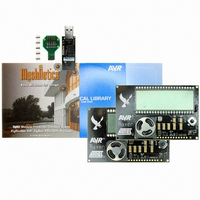
RZRAVEN 2.4 GHZ EVAL KIT
Manufacturer
Atmel
Type
802.15.4/Zigbeer
Datasheet
1.ATAVRRZUSBSTICK.pdf
(27 pages)
Specifications of ATAVRRZRAVEN
Frequency
2.4GHz
Wireless Frequency
2.4 GHz
Interface Type
USB
For Use With/related Products
AT86RF230
Lead Free Status / RoHS Status
Lead free / RoHS Compliant


3.12.1 Programming Interface
3.12.2 Relay Interface
3.13 Voltage Measurement Interface
3.13.1 GPIO
8
AVR2016
Both the ATmega3290P and ATmega1284P can be programmed using either the
JTAG or ISP interface. JTAG programming can be facilitated by connecting a JTAG
ICE mkII to the 50-mil pin header J301 (ATmega3290P) and J204 (ATmega1284P). A
total of 5 50-mil pin headers and one 50-mil to 100-mil converter are supplied with the
RZRAVEN kit.
ISP programming can be performed by connecting an ISP enabled AVR programming
tool to the pin header J302 (ATmega3290P) and J205 (ATmega1284P). AVR tools
like STK500, AVRISP mkII and JTAGICE mkII can be used for this.
The AVRRAVEN does not come with these headers mounted. So it is up to the user
populating these. Wires could also be soldered in instead of the dual row headers.
A relay interface (Relay Positive and Negative) is available through J401. This
interface can be used with the AVRRAVEN running from external power. A switching
transistor is connected to PB6 on the ATmega3290P so that sufficient current can be
provided to the relay being driven. An external power source must be used if the relay
option is required. The AVRRAVEN must then be supplied with the rated voltage of
the relay.
Two of the pins in header J401 can be used for external voltage measurements,
however only one at the time. The possible voltage ranges are 0 to VCC or via a
voltage divider giving an approximate range of 0 to five times VCC. A simple voltage
divider is implemented to scale the measurement voltage. A diode bridge is also used
to prevent reverse polarity and to protect the ATmega3290P’s ADC channel 3.
Both the ATmega3290P and ATmega1284P are high pin count devices, and a
number of these are not used. These pins are available through the user IO headers;
J401, J201, J202 and J203. See Table 3-2 and Table 3-3 for further details.
Be aware that these pins do not have level converters and should thus not be
connected directly to an application board running on a different voltage level than the
AVRRAVEN.
Table 3-2. ATmega3290P User IO
ATmega3290P Port Pin
PE3
PE4
PE5
PE6
PCB Connection
J401 –8
J401-9
J401-10
J401-11
Comment
Via 470Ω series resistor
and10kΩ pull-up
Via 470Ω series resistor
and10kΩ pull-up
Via 470Ω series resistor
and10kΩ pull-up
Via 470Ω series resistor
and10kΩ pull-up
8117D-AVR-04/08
Related parts for ATAVRRZRAVEN
Image
Part Number
Description
Manufacturer
Datasheet
Request
R


Part Number:
Description:
DEV KIT FOR AVR/AVR32
Manufacturer:
Atmel
Datasheet:

Part Number:
Description:
INTERVAL AND WIPE/WASH WIPER CONTROL IC WITH DELAY
Manufacturer:
ATMEL Corporation
Datasheet:
Part Number:
Description:
Low-Voltage Voice-Switched IC for Hands-Free Operation
Manufacturer:
ATMEL Corporation
Datasheet:
Part Number:
Description:
MONOLITHIC INTEGRATED FEATUREPHONE CIRCUIT
Manufacturer:
ATMEL Corporation
Datasheet:
Part Number:
Description:
AM-FM Receiver IC U4255BM-M
Manufacturer:
ATMEL Corporation
Datasheet:
Part Number:
Description:
Monolithic Integrated Feature Phone Circuit
Manufacturer:
ATMEL Corporation
Datasheet:
Part Number:
Description:
Multistandard Video-IF and Quasi Parallel Sound Processing
Manufacturer:
ATMEL Corporation
Datasheet:
Part Number:
Description:
High-performance EE PLD
Manufacturer:
ATMEL Corporation
Datasheet:
Part Number:
Description:
8-bit Flash Microcontroller
Manufacturer:
ATMEL Corporation
Datasheet:
Part Number:
Description:
2-Wire Serial EEPROM
Manufacturer:
ATMEL Corporation
Datasheet: