DV164102 Microchip Technology, DV164102 Datasheet - Page 10
DV164102
Manufacturer Part Number
DV164102
Description
KIT DEV RFPICKIT KIT 1
Manufacturer
Microchip Technology
Series
rfPIC™r
Type
rfPICr
Specifications of DV164102
Frequency
315MHz, 433MHz
Modulation
ASK
Silicon Manufacturer
Microchip
Silicon Core Number
RfPIC12F675, RfRXD0420/0920
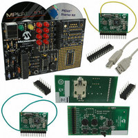
Kit Contents
Starter Kit, 433.92 MHz Transmitter And Receiver, 315 MHz Transmitter And Receiver, Software
Rohs Compliant
NA
For Use With/related Products
rfPIC12F675 and rfRXD0420,0920
Lead Free Status / RoHS Status
Lead free / RoHS Compliant
Lead Free Status / RoHS Status
Lead free / RoHS Compliant, Lead free / RoHS Compliant
Other names
Q1594003
Available stocks
Company
Part Number
Manufacturer
Quantity
Price
Company:

Part Number:
DV164102
Manufacturer:
Microchip Technology
Quantity:
135


rfPIC™ Development Kit 1 User’s Guide
1.4
DS70093A-page 6
GETTING STARTED WITH THE rfPIC DEVELOPMENT KIT 1
The transmitter modules come pre-programmed with a transmitter demonstration. The
enclosed PIC16F676 is programmed with a receiver demonstration program. Together
they demonstrate an on-off command and control application.
The PICkit 1 FLASH Starter Kit serves as a low-cost development and demonstration
platform for the transmitter and receiver modules.
To see your rfPIC Development Kit 1 in action, perform the following steps:
1.4.1
Step 1:
Familiarize yourself with the PICkit 1 FLASH Starter Kit operation by reading the
PICkit™ 1 FLASH Starter Kit User’s Guide (DS40051) and performing some of the
tutorials. Familiarity with the PICkit Starter Kit will be assumed throughout this user’s
guide.
Step 2:
Remove power from the PICkit Starter Kit by disconnecting the USB cable.
Step 3:
Remove the PIC12F675 from the PICkit Starter Kit evaluation socket.
Step 4:
Insert the PIC16F676 into the PICkit Starter Kit evaluation socket. See Figure 1-1.
Step 5:
Insert a receiver module (315 or 433.92 MHz) into the PICkit Starter Kit expansion
header J3. Make certain that the receiver module is oriented correctly. See Figure 1-1.
Step 6:
Insert the wire antenna into the antenna connector on the receiver module. See
Figure 1-1. The wire antenna length is determined by the receive frequency. For the
corresponding frequency, insert the following wire antenna:
FIGURE 1-1:
433.92 MHz
Frequency
315 MHz
USB Cable
Preparing the Receiver Module for Operation
Antenna Length
rfPIC RECEIVER DEMONSTRATION
LED D1
9-3/8”
6-3/4”
Preliminary
Expansion
Header (J3)
Wire Antenna
rfRXD Receiver Module
LED D0
© 2003 Microchip Technology Inc.
PICkit™ FLASH Starter Kit
Insert PIC16F676
Related parts for DV164102
Image
Part Number
Description
Manufacturer
Datasheet
Request
R

Part Number:
Description:
Manufacturer:
Microchip Technology Inc.
Datasheet:
Part Number:
Description:
Manufacturer:
Microchip Technology Inc.
Datasheet:
Part Number:
Description:
Manufacturer:
Microchip Technology Inc.
Datasheet:
Part Number:
Description:
Manufacturer:
Microchip Technology Inc.
Datasheet:
Part Number:
Description:
Manufacturer:
Microchip Technology Inc.
Datasheet:
Part Number:
Description:
Manufacturer:
Microchip Technology Inc.
Datasheet:
Part Number:
Description:
Manufacturer:
Microchip Technology Inc.
Datasheet:
Part Number:
Description:
Manufacturer:
Microchip Technology Inc.
Datasheet: