ATAVRRZ201 Atmel, ATAVRRZ201 Datasheet - Page 14
ATAVRRZ201
Manufacturer Part Number
ATAVRRZ201
Description
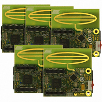
KIT RZ201 CTLR BOARDS & SOFTWARE
Manufacturer
Atmel
Series
AVR®r
Type
802.15.4/Zigbeer
Specifications of ATAVRRZ201
Frequency
2.4GHz
Wireless Frequency
2.4 GHz
Interface Type
JTAG
Antenna
PCB Trace
Silicon Manufacturer
Atmel
Silicon Core Number
ATmega1281V, AT86RF230
Kit Application Type
Wireless Connectivity
Application Sub Type
ZigBee Wireless Network
Silicon Family Name
ZigBee
Rohs Compliant
Yes
For Use With/related Products
AT86RF230
Lead Free Status / RoHS Status
Lead free / RoHS Compliant


5183A–ZIGB–12/07/06
4.2
4.3
4-2
End Device
Association &
Network
Configuration
Network
Operation
As each End Device is turned on, it performs an active scan of all channels from 11 to
26, broadcasting a Beacon Request and recording all information that it receives from all
PAN Coordinator beacons. The End Device will then select the channel that corre-
sponds to the PAN Coordinator with the correct PAN ID value that it is searching for.
The End Device will attempt to “associate” to the PAS Coordinator. Sucessful associa-
tion will result in a network address assignment to the End Device. By default, the
software in this kit assigns the first associated End Device the function of LED (output),
the second associated End Device the function of Switch 1 (input), the third – Switch 2,
and the fourth – Switch 3. Pressing SW1 on the PAN Coordinator completes the config-
uration of the network and allows the End Devices to operate as defined.
Now that the network configuration is complete, pressing the pushbutton switch (T1) on
the End Device corresponding to Switch 1 will send a message to the PAN Coordinator
to notify the End Device corresponding to LED, D1, to toggle its state. Similarly, End
Devices corresponding to Switches 2 and 3 control LEDs D2 and D3 respectively. Addi-
tional End Device information is captured and displayed on the LCD screen during
normal network operation. This includes the total number of times Switch 1, 2, and 3
were pressed, the power level in dBm of the received packet betwen the End Device
and the PAN, as well as the current state of each LED. Additional details with regard to
changing the network configuration are described in the next section.
Demonstration Kit User Guide
Related parts for ATAVRRZ201
Image
Part Number
Description
Manufacturer
Datasheet
Request
R

Part Number:
Description:
DEV KIT FOR AVR/AVR32
Manufacturer:
Atmel
Datasheet:

Part Number:
Description:
INTERVAL AND WIPE/WASH WIPER CONTROL IC WITH DELAY
Manufacturer:
ATMEL Corporation
Datasheet:
Part Number:
Description:
Low-Voltage Voice-Switched IC for Hands-Free Operation
Manufacturer:
ATMEL Corporation
Datasheet:
Part Number:
Description:
MONOLITHIC INTEGRATED FEATUREPHONE CIRCUIT
Manufacturer:
ATMEL Corporation
Datasheet:
Part Number:
Description:
AM-FM Receiver IC U4255BM-M
Manufacturer:
ATMEL Corporation
Datasheet:
Part Number:
Description:
Monolithic Integrated Feature Phone Circuit
Manufacturer:
ATMEL Corporation
Datasheet:
Part Number:
Description:
Multistandard Video-IF and Quasi Parallel Sound Processing
Manufacturer:
ATMEL Corporation
Datasheet:
Part Number:
Description:
High-performance EE PLD
Manufacturer:
ATMEL Corporation
Datasheet:
Part Number:
Description:
8-bit Flash Microcontroller
Manufacturer:
ATMEL Corporation
Datasheet:
Part Number:
Description:
2-Wire Serial EEPROM
Manufacturer:
ATMEL Corporation
Datasheet: