DVK-BTM521 Laird Technologies, DVK-BTM521 Datasheet - Page 80
DVK-BTM521
Manufacturer Part Number
DVK-BTM521
Description
BT MM DEV KIT
Manufacturer
Laird Technologies
Type
Transceiver, Bluetoothr
Specifications of DVK-BTM521
Frequency
2.4GHz
Interface Type
RS-232
Processor Series
BTM521
Silicon Manufacturer
Laird Technologies
Kit Application Type
Communication & Networking
Application Sub Type
Bluetooth
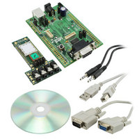
Kit Contents
Development Board & Software Tools
Features
Supports CSR
Rohs Compliant
Yes
For Use With/related Products
BTM521
Lead Free Status / RoHS Status
Lead free / RoHS Compliant
Lead Free Status / RoHS Status
Lead free / RoHS Compliant, Lead free / RoHS Compliant
Other names
DVK-BTM521
Available stocks
Company
Part Number
Manufacturer
Quantity
Price
Company:

Part Number:
DVK-BTM521-01
Manufacturer:
LAIRD
Quantity:
7


BTM520/521
Bluetooth
AT COMMAND SET
REFERENCE
80 www.lairdtech.com
®
Multimedia Plus Module
Hardware Units (BTM520 / 521)
This section covers S-Registers and AT-Commands that are related to hardware units of a BTM520 or BTM521
device. For this section, please also refer to the bluecore data sheet [10] for more detailed information.
Task
Enable DUN profile
Set up escape mode via
DSR, high throughput
Initiate DUN connection
Release DUN connection
1. Audio Loopback Mode
2. Codec Gain
For testing purposes, an audio loopback mode is available. In mode=1 audio input (ADC) and audio
output (DAC) are connected directly. In mode = 2, the stereo audio input signal is fed through the
Kalimba DSP with running SBC codec (encoder, decoder) and is directed back to the audio stereo
output. Audio Loopback Mode is controlled with the new AT Command “AT+BTL”.
Analogue input and output gains (Input Amplifier, Output Amplifier, Figure 3.25) can be set to one
of 23 steps called “Gain Level”. To each gain level, an overall gain (dBr) is assigned, according to
Table 3.40. The overall gain is formed by an analogue and a digital component as outlined in Table
3.40. Gain values can be specified either as gain level or as overall gain by separate S Registers.
Please note that a pair of such S-Registers always updates the other corresponding S-Register
(e.g., S589 – S689 and S590 – S690).
For S689 and S690, the overall gain (dBr) must be entered multiplied by 10. If the input value doesn’t
match a gain table entry, the nearest possible value is set. The actually set value can be checked by
reading back S689/S690. The value of S689/S690 is printed out multiplied by 10 in order to avoid
non integer numbers.
The command class “AT+G…” enables incremental and decremental gain settings. The increment/
decrement command corresponds to one row up/down in the gain table (Table 3.40). The Gain level
registers S589/S689 and S590/S690 are not affected by increment/decrement commands. Instead,
the current gain level is cached and can be retrieved by “AT+G(I|O)?”. There are two further commands
to restore the cached gain level from S589/S590 (“AT+G(I|O)R”) and to save the currently cached gain
level to S589/S590 (“AT+G(I|O)S”).
Task
Set audio loopback mode
Set sampling rate for Audio
Loopback Mode
Table 3.34: DUN – Summary of S Registers and AT Commands
Table 3.39: Audio Loopback AT-commands and S-Registers
AT-Command / S Register
S102
ATS507=2
AT+DUD<bd_addr
AT+DUH
AT-Command / SRegister
AT+BTL<Mode>
S419 [0..6], default=6
hex
>
Comment
0x04 = DUN (bitmask),
needs subsequent “AT&W” and “ATZ” to activate
Needs subsequent “AT&W” if desired as permanent
setting
Responses:
successful: “CONNECT 123456789012,1103,>”
failed: “NO CARRIER”
profile disabled: “ERROR 59”
incorrect state: “ERROR 63”
Responses:
successful: “NO CARRIER 1103”
profile disabled: “ERROR 59”
incorrect state: “ERROR 63”
Comment
Mode:
0 = off
1 = on, ADC -> DAC
2 = on, ADC -> DSP -> DAC
0 = 8 kHz
1 = 11.025 kHz
2 = 16 kHz
3 = 22.050 kHz
4 = 24 kHz
5 = 32 kHz
6 = 44.1 kHz
Laird Technologies
Related parts for DVK-BTM521
Image
Part Number
Description
Manufacturer
Datasheet
Request
R

Part Number:
Description:
BLUETOOTH EVAL BOARD BTM511
Manufacturer:
Laird Technologies
Datasheet:

Part Number:
Description:
Bluetooth / 802.15.1 Modules & Development Tools BLUETTH AT Data MODLE, No ANT DEVKIT
Manufacturer:
Laird Technologies
Part Number:
Description:
Bluetooth / 802.15.1 Modules & Development Tools BLUETTH Multimed MODLE, No ANT DEVKIT
Manufacturer:
Laird Technologies
Datasheet:

Part Number:
Description:
BLUETOOTH MODULE DEVELOPMENT KIT
Manufacturer:
Laird Technologies
Part Number:
Description:
Bluetooth 2.0 AT Data Module, Internal Antenna Development Kit
Manufacturer:
Laird Technologies
Part Number:
Description:
Bluetooth / 802.15.1 Modules & Development Tools BLUETTH HCI Data MDLE INTRNLANT DVKIT
Manufacturer:
Laird Technologies
Datasheet:
Part Number:
Description:
Bluetooth / 802.15.1 Modules & Development Tools BLUETTHMultimedMODLE Plus No Ant DEVKIT
Manufacturer:
Laird Technologies
Part Number:
Description:
Bluetooth / 802.15.1 Modules & Development Tools BLUETTH HCI Data MDLE No ANT DVKIT
Manufacturer:
Laird Technologies
Datasheet:

Part Number:
Description:
KIT FOR PRM113
Manufacturer:
Laird Technologies
Datasheet:

Part Number:
Description:
DEV KIT PRM122
Manufacturer:
Laird Technologies
Datasheet:
Part Number:
Description:
DEV KIT PRM123
Manufacturer:
Laird Technologies
Datasheet:

Part Number:
Description:
KIT FOR PRM112
Manufacturer:
Laird Technologies
Datasheet:
Part Number:
Description:
DEV KIT PRM121
Manufacturer:
Laird Technologies
Datasheet:

Part Number:
Description:
KIT DEVELOPMENT FOR LT2510 U.FL
Manufacturer:
Laird Technologies
Datasheet:

Part Number:
Description:
Bluetooth / 802.15.1 Modules Class2 v2.1+EDR Kit AT Data, Int Ant,SSP
Manufacturer:
Laird Technologies Wireless M2M
Datasheet: