BR-EVAL2.0 BlueRadios Inc, BR-EVAL2.0 Datasheet - Page 13
BR-EVAL2.0
Manufacturer Part Number
BR-EVAL2.0
Description
EVAL KIT BLUETOOTH VER2.0
Manufacturer
BlueRadios Inc
Type
Bluetooth V 2.0r
Datasheet
1.BR-EVAL2.0.pdf
(103 pages)
Specifications of BR-EVAL2.0
Frequency
2.4GHz
For Use With/related Products
Bluetooth
Lead Free Status / RoHS Status
Contains lead / RoHS non-compliant
Other names
822-1001


You can connect the RS-232 DB-9 evaluation board directly to the PC without an RS-232 pass through cable or
null modem.
Power Terminals for Evaluation Board
Inputs on J9 & J10 can be >5VDC and <12.0VDC. Worst case power draw for the entire evaluation board is
150ma when the Bluetooth radio/modem connection is established and transmitting. Power consumption is much
lower depending on parameter settings.
Hardware UART Communications Connections for Modules and Eval Board
Radio module TX UART → RX of the application Micro Controller Unit (MCU)
Radio module RX UART← TX of the application Micro Controller Unit (MCU)
Radio module RTS UART→ CTS of the application Micro Controller Unit (MCU)
Radio module CTS UART← RTS of the application Micro Controller Unit (MCU)
PCMIF (Audio)
The module supports 13 bits Linear CODEC interface and the module is configured as master mode of PCM I/F.
1) PCM_OUT, PCM_IN, PCM_CLK, and PCM_SYNC carry one of bi-directional channel of voice data using 13bits
PCM at 8ks/s.
2) PCM_SYNC is output and operates at a fixed clock frequency of 8kHz.
3) PCM_CLK is output and operates at a fixed clock frequency of 256kHz.
4) Reference PCM audio device is Motorola MC145483 13 bit linear CODEC or Windbond W681360R
(recommended for new designs)
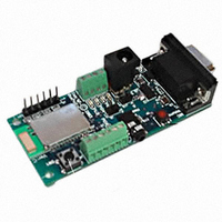
Evaluation Board Block Diagram
LEDs
The
the PIO(2) should go-on whenever the unit is connected to another Bluetooth device. The remaining
are defined for the following PIO table:
7173 S. Havana Street, Suite 600
RED
Push Button Switch (PIO4)
Triple Purpose
LED next to power terminals should come on whenever the unit has power supplied. The
RS-
232
J1
Female DB-9
Level
shifting
circuit
www.BlueRadios.com
PIO(2,3,4,5)
•
J3
Englewood, CO 80112
0-3.3Vdc max.
directly into radio
UART (Not 5Vdc)
J4
Copyright © 2002-2008
BlueRadios, Inc.
Page 13 of 103
BlueRadios
Bluetooth
SMT Module
o o o o o o o
Reserved
CPU Reset (SW1)
Active
•
Tel (303) 957-1003
Low
BR-AT_COMMANDS-100 Rev. 3.6.2.1.4.0
PIO(6,7) not connected on
the evaluation board.
•
sales@BlueRadios.com
Blue
Green
LED on
LED’s
Related parts for BR-EVAL2.0
Image
Part Number
Description
Manufacturer
Datasheet
Request
R

Part Number:
Description:
RF EVAL FOR BR-LE4.0 BLE
Manufacturer:
BlueRadios Inc
Datasheet:

Part Number:
Description:
EVAL BOARD BLUETOOTH VER2.0
Manufacturer:
BlueRadios Inc
Datasheet:

Part Number:
Description:
MODULE BT CLASS 1 W/ANT HCI FW
Manufacturer:
BlueRadios Inc
Datasheet:

Part Number:
Description:
TEST BOARD BLUESTAMP V2.0 18DIP
Manufacturer:
BlueRadios Inc
Datasheet:

Part Number:
Description:
USB NANO DONGLE BLUETOOTH VER2.1
Manufacturer:
BlueRadios Inc
Datasheet:

Part Number:
Description:
MODULE BT CLASS 2 ANT® HCI FW
Manufacturer:
BlueRadios Inc
Datasheet:
Part Number:
Description:
MODULE BLUETOOTH VER2.0 W/ANT
Manufacturer:
BlueRadios Inc
Datasheet:

Part Number:
Description:
MODULE BT CLASS 1 WO/ANT HCI FW
Manufacturer:
BlueRadios Inc
Datasheet:


Part Number:
Description:
MODULE BT CLASS 2 HCI NO ANT
Manufacturer:
BlueRadios Inc
Datasheet:

Part Number:
Description:
MODULE BLUETOOTH VER2.0 NO ANT
Manufacturer:
BlueRadios Inc
Datasheet:

Part Number:
Description:
MODULE BLUETOOTH V2.0 W/ANT®
Manufacturer:
BlueRadios Inc
Datasheet:

Part Number:
Description:
MODULE BLUESTAMP VER2.0 NO ANT
Manufacturer:
BlueRadios Inc
Datasheet:
