JN5148-EK010 Jennic LTD, JN5148-EK010 Datasheet
JN5148-EK010
Specifications of JN5148-EK010
935294044596
JN5148-EK010


Related parts for JN5148-EK010


JN5148-EK010 Summary of contents
Page 1
... JN5148-EK010 Evaluation Kit User Guide JN-UG-3062 Revision 2.1 25 November 2010 ...
Page 2
... JN5148-EK010 Evaluation Kit User Guide 2 © NXP Laboratories UK 2010 JN-UG-3062 v2.1 ...
Page 3
... Demo System Overview 3.2 Setting Up the Demo System 3.3 Monitoring Sensor Measurements 3.3.1 Network Screens 3.3.2 Node Screens 3.3.3 Node Control Screens 3.3.4 Settings Screen 3.4 Lighting Control 3.5 Routing Experiment JN-UG-3062 v2.1 © NXP Laboratories UK 2010 JN5148-EK010 Evaluation Kit User Guide ...
Page 4
Contents 4. Where Next? 4.1 Which Protocol? 4.2 User Documentation 4.2.1 IEEE 802.15.4 Documentation 4.2.2 JenNet Documentation 4.2.3 ZigBee PRO Documentation 4.3 Software Developer’s Kit (SDK) Appendices A. Button Functions in Demonstration A.1 Controller Board Buttons A.2 Sensor Board Buttons ...
Page 5
... About this Manual This manual provides a guide to setting up a simple wireless network based on the JN5148-EK010 Evaluation Kit. The manual also describes how to run the supplied Home Sensor Demonstration on the resulting system. The demonstration application is based on the JenNet wireless network protocol, but you can also use this evaluation kit along with the JN5148 Software Developer’ ...
Page 6
About this Manual Acronyms and Abbreviations API Application Programming Interface JenNet Jennic Network SDK Software Developer’s Kit Related Documents JN-AN-1065 JenNet Home Sensor Demonstration Application Note JN-UG-3007 JN51xx Flash Programmer User Guide Feedback Address If you wish to comment on ...
Page 7
... Introduction to the Evaluation Kit Welcome to the JN5148-EK010 Evaluation Kit. This kit allows a small wireless network to be quickly assembled and used with a pre-loaded demonstration application. The evaluation kit can also be used in conjunction with the JN5148 Software Developer’s Kit (SDK) to develop new applications. ...
Page 8
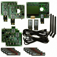
... Chapter 1 Introduction to the Evaluation Kit 1.1 Kit Contents In the JN5148-EK010 Evaluation Kit, you will find the following components (numbers refer to Figure 1 Controller board with LCD and pre-installed module with uFl connector Sensor boards: 2 with pre-installed module with uFl connector* 2 with pre-installed module with integrated PCB antenna 3 ...
Page 9
... Kit Hardware The JN5148-EK010 Evaluation Kit includes 5 boards which can act as wireless network nodes: 4 Sensor boards and a Controller board. These boards are illustrated and described below, as well as the JN5148-based modules that fit onto the boards. 1.2.1 Sensor Board The 4 Sensor boards are physically identical and each board is pre-installed with a plug-in (removable) module containing the JN5148 microcontroller ...
Page 10
Chapter 1 Introduction to the Evaluation Kit D9 1.2.2 Controller Board The Controller board is a DR1047 board with the following features (also refer to Figure 3): Large 128 x 64 pixel LCD screen with a comprehensive set of driver ...
Page 11
... SW6 J8 J9 J11 1.2.3 Modules Three types of JN5148-based module are supplied in the JN5148-EK010 Evaluation Kit: Two modules with an integrated PCB antenna - these modules are pre-installed on two of the Sensor boards Three modules mounted on uFl-to-SMA adaptor boards, each having an SMA connector which can accept one of the supplied screw-on antennae - these ...
Page 12
... The three module types are shown in the photograph below - from left to right, standard-power module with ceramic antenna, standard-power module with SMA connector and high-power module with SMA connector (note that the high-power module is longer than the equivalent standard-power module). 12 Figure 4: JN5148-Based Modules © NXP Laboratories UK 2010 JN-UG-3062 v2.1 ...
Page 13
... JN-UG-3062 v2.1 Section 2.1 Section 2.2 Section 2.3 Section 2.4 ..... ~ 4 Figure 5: 2400-MHz RF Band © NXP Laboratories UK 2010 JN5148-EK010 Evaluation Kit User Guide Section 4.2). 2480 MHz Ch26 13 ...
Page 14
Chapter 2 Wireless Network Concepts 2.2 Node Types In addition to running an application (e.g. temperature measurement), each node of a wireless network has a networking role. A wireless network can contain three types of node, differentiated by their networking ...
Page 15
... Thus, a message for a remote node must be passed up the tree until it can passed down to its destination. JN-UG-3062 v2.1 2.1). Once this initialisation is complete, the Co-ordinator will Co-ordinator Figure 6: Star Network Figure © NXP Laboratories UK 2010 JN5148-EK010 Evaluation Kit User Guide 7. Any node can only 15 ...
Page 16
Chapter 2 Wireless Network Concepts Co-ordinator Router End Device The Tree topology is available in the IEEE 802.15.4 and JenNet protocols (in ZigBee PRO enhanced to a Mesh topology suitable for larger networks and higher traffic ...
Page 17
... Figure 9: Example Mesh Networks Note: Since the five evaluation kit boards are pre- programmed with JenNet software, they will form a Tree network when the demonstration is started (Mesh networks are not possible with JenNet). © NXP Laboratories UK 2010 JN5148-EK010 Evaluation Kit User Guide 17 ...
Page 18
... A number of C APIs (Application Programming Interfaces) are provided to allow a user application to easily interact with the layers of the stack. These APIs are supplied in the JN5148 SDK. The required APIs depend on the protocol used - APIs are available for IEEE 802.15.4, JenNet (known as the Jenie API) and ZigBee PRO. ...
Page 19
... Home Sensor Demonstration You are now going to set up a small wireless network, using the contents of the JN5148-EK010 Evaluation Kit, and run the JenNet Home Sensor Demonstration application that has been pre-programmed into the Flash memory devices of the boards. This chapter guides you through the set-up and operation of the demo system, as follows: 1 ...
Page 20
Chapter 3 Home Sensor Demonstration Router (Sensor board) End Device (Sensor board) Figure 11: Example Demo System Topology 3.2 Setting Up the Demo System This section describes how to assemble the demo system, using the Controller board and three Sensor ...
Page 21
... By default, the temperature measurement from each node will be displayed on the screen - this is the ‘Temperature’ screen of the Controller board application’s user interface (see the photograph below). JN-UG-3062 v2.1 © NXP Laboratories UK 2010 JN5148-EK010 Evaluation Kit User Guide 21 ...
Page 22
Chapter 3 Home Sensor Demonstration Step 7 Use the Home Sensor Demonstration You can now use the Home Sensor Demonstration to obtain temperature, humidity and light-level measurements from the Sensor boards. Operation of the demo system is described in Section ...
Page 23
... Settings Done "Bedroom" node "Lounge" node screen screen Node Control Control Done "Bedroom" node "Lounge" node control screen control screen © NXP Laboratories UK 2010 JN5148-EK010 Evaluation Kit User Guide "Bathroom" node screen Node Node Control Done Done "Bathroom" node control screen 23 ...
Page 24
Chapter 3 Home Sensor Demonstration 3.3.1 Network Screens Each network screen displays a particular type of sensor data for all network nodes: Temperature screen: This screen displays the temperature readings from all nodes, in degrees Celsius the first ...
Page 25
... The node control screen is used to configure the alarms that can be generated for the node. Figure 15: Node Control Screen (Bedroom) JN-UG-3062 v2.1 Section 3.3.3). © NXP Laboratories UK 2010 JN5148-EK010 Evaluation Kit User Guide Figure 14 below. 25 ...
Page 26
Chapter 3 Home Sensor Demonstration Four alarms can be configured: Temp high alarm: This is triggered when the temperature measured by the node rises to a pre-defined value. This alarm is enabled by setting the required trigger temperature on this ...
Page 27
... Allows the sensor readings from nodes to be displayed: • on: Readings from 4 nodes displayed • off: Readings from 3 nodes displayed Table 2: Settings Screen Parameters Sensor Board LED on Controller Board Hall D1 Bedroom D2 Lounge D3 Bathroom D4 Table 3: LED Control © NXP Laboratories UK 2010 JN5148-EK010 Evaluation Kit User Guide 27 ...
Page 28
Chapter 3 Home Sensor Demonstration 3.5 Routing Experiment The Sensor boards that are fitted with a ceramic antenna have been programmed as End Devices. The Sensor boards that are fitted with SMA connectors act as Routers - they relay messages ...
Page 29
... Note 2: Application access to the JN5148 on-chip peripherals is provided by the Integrated Peripherals API. In addition, Controller and Sensor board resources can be accessed using the Board API. Both APIs are included in the JN5148 SDK. © NXP Laboratories UK 2010 JN5148-EK010 Evaluation Kit User Guide 4 on page 30. 29 ...
Page 30
Chapter 4 Where Next? Criteria IEEE 802.15.4 Recommended Star Topologies Point-to-point * Maximum Network Size 50 nodes Network Recovery None Development Complexity Medium Available Application Co-ord/Router: 115 Kbytes Code Space *** End Device: 115 Kbytes Standards Compliance IEEE 802.15.4 standard ...
Page 31
... IEEE 802.15.4 Application Development Reference Manual (JN-RM-2024) which describes how to use the template. JN-UG-3062 v2.1 Section 4.2.1 Section 4.2.2 Section 4.2.3 Figure 17 on page 33. © NXP Laboratories UK 2010 JN5148-EK010 Evaluation Kit User Guide 31 ...
Page 32
... Details the Board API, used in application code to interact with components on the boards supplied in the evaluation kit. Describes how to install the JN5148 Soft- ware Developer’s Kit (SDK) and how to use the Eclipse development platform. Describes how to use the JN51xx Flash Programmer ...
Page 33
... Figure 17: Guide to Essential IEEE 802.15.4 Documentation JN-UG-3062 v2.1 © NXP Laboratories UK 2010 JN5148-EK010 Evaluation Kit User Guide 33 ...
Page 34
Chapter 4 Where Next? 4.2.2 JenNet Documentation A complete list of the user documentation relevant to JenNet is provided in below. In addition, a visual guide to using the essential JenNet documentation is provided in Figure 18 If you intend ...
Page 35
... Describes how to install the JN5148 Soft- ware Developer’s Kit (SDK) and how to use the Eclipse development platform. Describes how to use the JN51xx Flash Programmer. Table 6: JenNet User Documentation © NXP Laboratories UK 2010 JN5148-EK010 Evaluation Kit User Guide 35 ...
Page 36
Chapter 4 Where Next? Figure 18: Guide to Essential JenNet Documentation 36 © NXP Laboratories UK 2010 JN-UG-3062 v2.1 ...
Page 37
... ZigBee PRO Smart Energy API User Guide (JN-UG-3059). The Application Note ZigBee PRO Smart Energy Demonstration (JN-AN-1135) provides a useful example Smart Energy application to which you should refer. JN-UG-3062 v2.1 Figure 19 on page 39. © NXP Laboratories UK 2010 JN5148-EK010 Evaluation Kit User Guide 37 ...
Page 38
... Details the functions and associated resources used to interact with components on the boards supplied in the evaluation kit. Describes how to install the JN5148 Software Developer’s Kit (SDK) and how to use the Eclipse development platform. Describes how to use the JN51xx Flash Pro- grammer to load application binaries into net- work nodes ...
Page 39
... Figure 19: Guide to Essential ZigBee PRO Documentation JN-UG-3062 v2.1 © NXP Laboratories UK 2010 JN5148-EK010 Evaluation Kit User Guide 39 ...
Page 40
... JN51xx Integrated Peripherals API for interacting with on-chip peripherals LPRF Board API for interacting with evaluation kit board resources Installation instructions for the JN5148 SDK and the Eclipse plug-ins are provided in the JN5148 SDK Installation and User Guide (JN-UG-3064). 40 Note: The installers for the JN5148 SDK Libraries and Toolchain are available from www ...
Page 41
... Go to Temperature screen, which shows temperature readings ( for all nodes Humidity screen, which shows relative humidity readings (%) for all nodes Light screen, which shows light-level readings for all nodes. © NXP Laboratories UK 2010 JN5148-EK010 Evaluation Kit User Guide ...
Page 42
Appendices Node Screens (Hall, Bedroom, Lounge, Bathroom) Button Label SW1 Node SW2 Control SW3 SW4 Node Control Screens Button Label SW1 Select SW2 + SW3 - SW4 Done Table 11: Button Functions for Node Control Screens Settings Screen Button Label ...
Page 43
... Extinguish LED D3 on the Controller board. Extinguish LED D4 on the Controller board. Illuminate LED D1 on the Controller board. Illuminate LED D2 on the Controller board. Illuminate LED D3 on the Controller board. Illuminate LED D4 on the Controller board. © NXP Laboratories UK 2010 JN5148-EK010 Evaluation Kit User Guide 43 ...
Page 44
... You should load a binary file into the Flash memory of a board using the JN51xx Flash programmer, which is provided as part of the JN5148 SDK - the tool is provided in the SDK Toolchain (JN-SW-4041). Flash programming is fully described in the JN51xx Flash Programmer User Guide (JN-UG-3007). ...
Page 45
... References to Jenie/JenNet patch removed, note added on re-starting demonstration from scratch and board component lists modified Pre-loaded Home Sensor Demo application changed from ZigBee PRO to JenNet. Minor corrections and terminology changes made © NXP Laboratories UK 2010 JN5148-EK010 Evaluation Kit User Guide 45 ...
Page 46
... JN5148-EK010 Evaluation Kit User Guide Important Notice Jennic reserves the right to make corrections, modifications, enhancements, improvements and other changes to its products and services at any time, and to discontinue any product or service without notice. Customers should obtain the latest relevant information before placing orders, and should verify that such information is current and complete. ...