STEVAL-TDR001V1 STMicroelectronics, STEVAL-TDR001V1 Datasheet
STEVAL-TDR001V1
Specifications of STEVAL-TDR001V1
Available stocks


Related parts for STEVAL-TDR001V1


STEVAL-TDR001V1 Summary of contents
Page 1
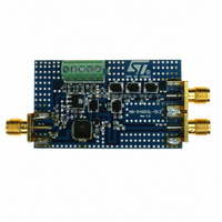
... max APC ■ Beo free amplifier ■ RoHS compliant Description The STEVAL-TDR001V1 is a two stage RF power amplifier which includes a low pass output filter for harmonics rejection specifically designed for portable two-way UHF radio communication. March 2010 STEVAL-TDR001V1 Mechanical specification mm Table 1. ...
Page 2
... Maximum ratings . . . . . . . . . . . . . . . . . . . . . . . . . . . . . . . . . . . . . . . . . . . . 3 2 Electrical characteristics . . . . . . . . . . . . . . . . . . . . . . . . . . . . . . . . . . . . . 3 3 Typical performance . . . . . . . . . . . . . . . . . . . . . . . . . . . . . . . . . . . . . . . . . 4 4 Circuit layout . . . . . . . . . . . . . . . . . . . . . . . . . . . . . . . . . . . . . . . . . . . . . . . 8 5 Circuit schematic . . . . . . . . . . . . . . . . . . . . . . . . . . . . . . . . . . . . . . . . . . . 9 6 Package mechanical data . . . . . . . . . . . . . . . . . . . . . . . . . . . . . . . . . . . . 10 6.1 PowerFLAT™ mechanical data . . . . . . . . . . . . . . . . . . . . . . . . . . . . . . . . 11 6.1.1 6.2 Thermal pad and via design SOT- 6.2.1 7 Revision history . . . . . . . . . . . . . . . . . . . . . . . . . . . . . . . . . . . . . . . . . . . 17 2/18 Mounting indications . . . . . . . . . . . . . . . . . . . . . . . . . . . . . . . . . . . . . . . 13 Soldering profile . . . . . . . . . . . . . . . . . . . . . . . . . . . . . . . . . . . . . . . . . . . 15 Doc ID 17336 Rev 1 STEVAL-TDR001V1 ...
Page 3
... STEVAL-TDR001V1 1 Electrical data 1.1 Maximum ratings Table 2. Absolute maximum ratings Symbol CASE Electrical characteristics T = +25 ° Table 3. Electrical specification Symbol Freq. Frequency range OUT TOTAL OUT PAE @ P OUT VAPC @ P OUT Harmonics @ P OUT Parameter Supply voltage Drain current Operating case temperature Max. ambient temperature = 7 ...
Page 4
... Figure -10 -12 -14 -16 -18 500 550 600 300 Doc ID 17336 Rev 1 STEVAL-TDR001V1 Output power vs frequency q y VDD=5V VDD=7V VDD=9V 380 400 420 440 460 480 500 Freq (MHz) Input return loss vs frequency Vdd = 7.2V Pin = 10dBm Vapc = 4.6V 350 ...
Page 5
... STEVAL-TDR001V1 Figure 5. Low pass filter - insertion loss -5 -15 -25 -35 -45 -55 -65 -75 1.0E+08 Figure 6. Low pass filter - input return loss 0 -5 -10 -15 -20 -25 -30 -35 1.0E+08 3.0E+08 5.0E+08 7.0E+08 F(Hz) Low pass filter - Input Return Loss 3.0E+08 5.0E+08 7.0E+08 F(Hz) Doc ID 17336 Rev 1 Typical performance 9 ...
Page 6
... Tyco/electronics 2 CRG series thick film chip neohn Tyco/electronics 2 CRG series thick film chip neohn Tyco/electronics 1 CRG series thick film chip neohn Doc ID 17336 Rev 1 STEVAL-TDR001V1 Part code Size 603 603 603 603 603 603 603 603 603 603 603 603 603 ...
Page 7
... STEVAL-TDR001V1 Table 4. Part list (continued) Designator Value Quantity TL2 50 TL3 TL4 Manufacturer Doc ID 17336 Rev 1 Typical performance Part code Size L=9.8 mm W=0.92 mm L=9.8 mm W=0. Ω 7/18 ...
Page 8
... Circuit layout 4 Circuit layout Figure 7. Test fixture component layout 8/18 Doc ID 17336 Rev 1 STEVAL-TDR001V1 ...
Page 9
... STEVAL-TDR001V1 5 Circuit schematic Figure 8. Circuit schematic Figure 9. Filter schematic Doc ID 17336 Rev 1 Circuit schematic 9/18 ...
Page 10
... Package mechanical data 6 Package mechanical data In order to meet environmental requirements, ST offers these devices in different grades of ® ECOPACK packages, depending on their level of environmental compliance. ECOPACK specifications, grade definitions and product status are available at: www.st.com. ECOPACK trademark. 10/18 Doc ID 17336 Rev 1 STEVAL-TDR001V1 ® ...
Page 11
... STEVAL-TDR001V1 6.1 PowerFLAT™ mechanical data Table 5. PowerFLAT™ mechanical data Dim Figure 10. PowerFLAT™ package dimensions mm Min. Typ. Max. 0.90 1.00 0.02 0.05 0.24 0.15 0.25 0.35 0.43 0.51 0.58 0.64 0.71 0.79 5.00 0.30 5.00 2.49 2.57 2.64 1.27 3 ...
Page 12
... PowerFLAT™ tape and reel dimensions Dim Figure 11. PowerFLAT™ tape and reel 12/18 mm. Min. Typ Max. 5.15 5.25 5.35 5.15 5.25 5.35 1.0 1.1 1.2 Doc ID 17336 Rev 1 STEVAL-TDR001V1 inch Min. Typ Max. 0.12 0.13 0.13 0.12 0.13 0.13 0.02 0.02 0.02 ...
Page 13
... STEVAL-TDR001V1 6.1.1 Mounting indications Figure 12. Standard SMD mounting Doc ID 17336 Rev 1 Package mechanical data 13/18 ...
Page 14
... The via pattern is based on thru-hole vias with 0.203 mm to 0.330 mm finished hole size 1.2 mm grid pattern with 0.025 plating on via walls. If micro vias are used in a design suggested that the quantity of vias be increased by a 4:1 ratio to achieve similar results. Figure 13. Pad layout details 14/18 Doc ID 17336 Rev 1 STEVAL-TDR001V1 ...
Page 15
... STEVAL-TDR001V1 6.2.1 Soldering profile Figure 14 shows the recommeded solder for devices that have Pb-free terminal plating and where a Pb-free solder is used. Figure 14. Recommended solder profile Figure 15 shows the recommeded solder for devices with Pb-free terminal plating used with leaded solder, or for devices with leaded terminal plating used with a leaded solder. ...
Page 16
... Package mechanical data Figure 16. Reel information 16/18 Doc ID 17336 Rev 1 STEVAL-TDR001V1 ...
Page 17
... STEVAL-TDR001V1 7 Revision history Table 7. Document revision history Date 31-Mar-2010 Revision 1 Initial release. Doc ID 17336 Rev 1 Revision history Changes 17/18 ...
Page 18
... Australia - Belgium - Brazil - Canada - China - Czech Republic - Finland - France - Germany - Hong Kong - India - Israel - Italy - Japan - Malaysia - Malta - Morocco - Philippines - Singapore - Spain - Sweden - Switzerland - United Kingdom - United States of America 18/18 Please Read Carefully: © 2010 STMicroelectronics - All rights reserved STMicroelectronics group of companies www.st.com Doc ID 17336 Rev 1 STEVAL-TDR001V1 ...