4010-DAAKF_434 Silicon Laboratories Inc, 4010-DAAKF_434 Datasheet - Page 5
4010-DAAKF_434
Manufacturer Part Number
4010-DAAKF_434
Description
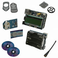
KIT DEV KEYFOB 434MHZ FOR SI4010
Manufacturer
Silicon Laboratories Inc
Series
EZRadio®r
Type
Key Fobr
Datasheets
1.4010-DAAKF_434.pdf
(2 pages)
2.4010-DAAKF_434.pdf
(14 pages)
3.4010-DKKF_434.pdf
(16 pages)
Specifications of 4010-DAAKF_434
Frequency
434MHz
Wireless Frequency
27 MHz to 960 MHz
Modulation
FSK, OOK
Output Power
10 dBm
Antenna
SMA
For Use With/related Products
Si4010
Lead Free Status / RoHS Status
Lead free / RoHS Compliant
Lead Free Status / RoHS Status
Lead free / RoHS Compliant, Lead free / RoHS Compliant
Other names
336-1981


3. EC3 debug adapter Programming adapter User’s own application
In this setup, the user can incorporate the debugging capabilities into the final application using a cheap 4-pin
header connection. Silicon Labs’ ToolStick USB Debug Adapter (not part of the development kit) is also compatible
with the key fob development platform and can be used in the above scenarios.
2. Debugging an Application
To debug an application the user is provided with the Silicon Laboratories IDE (Integrated Development
Environment). The IDE has an integral help. This section is not a user manual for the IDE, but highlights the items
which are important when working with the IDE.
2.1. Installing the IDE and USB Debug Adapters
The IDE gets installed into its own directory. The main executable file is IDE.exe. See the CD installation notes for
details. The IDE works with the USB Debug Adapter, shown in the section above. When the IDE recognizes the
Silicon Labs USB debug adapters, it queries whether its internal firmware is compatible with the Si4010. If not, then
it notifies the user and requests permission to update the adapter's firmware. Silicon Labs also provides a program,
usb_debug_adapter_firmware_reset.exe, to clear the adapter's firmware manually before connection to
the IDE. The program resides in the same directory as the IDE main executable.
With the Si4010 debugging chain it is required that the manual adapter firmware clearing is done for each USB
adapter before using the key fob debugging chain. That operation needs to be done only once per USB Debug
Adapter. The IDE will then program the correct firmware into the adapter.
The reset firmware executable will scan USB ports and give the user a list of connected Silicon Labs USB
adapters. The USB Debug Adapter name starts with EC. Users can have more than one USB adapter connected
to the computer.
2.2. Keil toolchain integration
The project files in examples assume that the Keil toolchain is installed into: C:\Keil directory. The location of
the Keil toolchain can be easily changed in the project files. An evaluation version of the Keil toolchain can be
downloaded from the Keil website at http://www.keil.com/. This free version has a 2 KB code limitation and starts
the code at the 0x0800 address. The Keil free evaluation version can be unlocked to become a 4 K version with no
code placement limitation by following the directions given in application note AN104 about Keil toolchain
integration and license management. Please contact your Silicon Laboratories sales representative or distributor
for application assistance.
2.3. IDE Features
The IDE allows the following:
1. Download the OMF-51 linker output format (Keil BL51 linker output, for example) and match the source
code lines with the compiled file. This allows source code debugging, including variable value viewing, set-
ting breakpoints, single-stepping, etc. Note that the output of the Keil LX51 linker is not understood by the
IDE.
Rev. 0.1
Si4010-Key Fob-DK
5
Related parts for 4010-DAAKF_434
Image
Part Number
Description
Manufacturer
Datasheet
Request
R

Part Number:
Description:
SMD/C°/SINGLE-ENDED OUTPUT SILICON OSCILLATOR
Manufacturer:
Silicon Laboratories Inc
Part Number:
Description:
Manufacturer:
Silicon Laboratories Inc
Datasheet:
Part Number:
Description:
N/A N/A/SI4010 AES KEYFOB DEMO WITH LCD RX
Manufacturer:
Silicon Laboratories Inc
Datasheet:
Part Number:
Description:
N/A N/A/SI4010 SIMPLIFIED KEY FOB DEMO WITH LED RX
Manufacturer:
Silicon Laboratories Inc
Datasheet:
Part Number:
Description:
N/A/-40 TO 85 OC/EZLINK MODULE; F930/4432 HIGH BAND (REV E/B1)
Manufacturer:
Silicon Laboratories Inc
Part Number:
Description:
EZLink Module; F930/4432 Low Band (rev e/B1)
Manufacturer:
Silicon Laboratories Inc
Part Number:
Description:
I°/4460 10 DBM RADIO TEST CARD 434 MHZ
Manufacturer:
Silicon Laboratories Inc
Part Number:
Description:
I°/4461 14 DBM RADIO TEST CARD 868 MHZ
Manufacturer:
Silicon Laboratories Inc
Part Number:
Description:
I°/4463 20 DBM RFSWITCH RADIO TEST CARD 460 MHZ
Manufacturer:
Silicon Laboratories Inc
Part Number:
Description:
I°/4463 20 DBM RADIO TEST CARD 868 MHZ
Manufacturer:
Silicon Laboratories Inc
Part Number:
Description:
I°/4463 27 DBM RADIO TEST CARD 868 MHZ
Manufacturer:
Silicon Laboratories Inc
Part Number:
Description:
I°/4463 SKYWORKS 30 DBM RADIO TEST CARD 915 MHZ
Manufacturer:
Silicon Laboratories Inc
Part Number:
Description:
N/A N/A/-40 TO 85 OC/4463 RFMD 30 DBM RADIO TEST CARD 915 MHZ
Manufacturer:
Silicon Laboratories Inc
Part Number:
Description:
I°/4463 20 DBM RADIO TEST CARD 169 MHZ
Manufacturer:
Silicon Laboratories Inc