1002-TCB1D434 Silicon Laboratories Inc, 1002-TCB1D434 Datasheet - Page 3
1002-TCB1D434
Manufacturer Part Number
1002-TCB1D434
Description
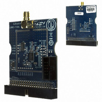
BOARD EVALUATION FOR SI1002
Manufacturer
Silicon Laboratories Inc
Type
Transceiver, ISMr
Specifications of 1002-TCB1D434
Mfg Application Notes
SI1000 Code Examples AppNote
Frequency
434MHz
Supply Voltage (min)
0.9 V
Product
RF Modules
Maximum Frequency
915 MHz
Output Power
13 dBm
Antenna
SMA
Supply Voltage (max)
3.6 V
For Use With/related Products
Si100x
Lead Free Status / RoHS Status
Lead free / RoHS Compliant
Lead Free Status / RoHS Status
Lead free / RoHS Compliant, Lead free / RoHS Compliant
Other names
336-1891


4. Connect the USB cable (which will supply power and USB communications).
5. Turn on power: SW5 ON
6. Download the LoadBoard Light code to each. (See "3. Silicon Laboratories IDE Code Download" on page 16).
7. Launch the WDS Chip Configurator application on your PC (Start Silicon Laboratories WDS3)
8. WDS should automatically detect the Si1000 connected via USB. The following screen will appear:
9. Click Radio Control Panel and Select.
10.Configure the radio to transmit a GFSK-modulated PN9 test message:
File location: C:\SiLabs\MCU\Examples\Si100x\EZRadioPRO\WDS_Support\lb_light.hex (Si100x) or
C:\SiLabs\MCU\Examples\Si101x\EZRadioPRO\WDS_Support\lb_light.hex (Si101x)
(Files installed automatically with the Silicon Labs IDE)
Note that the red LED, DS3, blinks when the LoadBoard Light firmware is running.
a. Select the TX state by clicking the TX button,.
b. Set the frequency (903 MHz shown).
c. Set the crystal load capacitance to 10.039 pF.
Rev. 0.1
Si1000/10 QSG
3
Related parts for 1002-TCB1D434
Image
Part Number
Description
Manufacturer
Datasheet
Request
R

Part Number:
Description:
LEAD, 36W CEN TO 25W D PLUG
Manufacturer:
VIDEK
Datasheet:

Part Number:
Description:
BOARD EVALUATION FOR SI1002
Manufacturer:
Silicon Laboratories Inc
Datasheet:

Part Number:
Description:
PCB Inserter/Extractor,0.093 In. PCB Width,1.937 In. Upturned Lever,Nylon,Black
Manufacturer:
Bivar Inc
Datasheet:
Part Number:
Description:
PCB Inserter/Extractor,0.093 In. PCB Width,1.937 In. Upturned Lever,Nylon,Natural
Manufacturer:
Bivar Inc
Datasheet:

Part Number:
Description:
TYPE Y OR Z CLASS I GROUP C-D, WITH PRESSURE SWITCH, 15 CU.FT.
Manufacturer:
PEPPERL & FUCHS

Part Number:
Description:
SMD/C�/SINGLE-ENDED OUTPUT SILICON OSCILLATOR
Manufacturer:
Silicon Laboratories Inc
Part Number:
Description:
Manufacturer:
Silicon Laboratories Inc
Datasheet:
Part Number:
Description:
N/A N/A/SI4010 AES KEYFOB DEMO WITH LCD RX
Manufacturer:
Silicon Laboratories Inc
Datasheet:
Part Number:
Description:
N/A N/A/SI4010 SIMPLIFIED KEY FOB DEMO WITH LED RX
Manufacturer:
Silicon Laboratories Inc
Datasheet: