370100632 Sigma Designs Inc, 370100632 Datasheet
370100632
Specifications of 370100632


Related parts for 370100632


370100632 Summary of contents
Page 1
Instruction Z-Wave Module Selection Guideline Document No.: INS10027 Version: 6 This document introduces the ZW0201, and ZW0301 Single Description: Chip based Z-Wave Module families, and suggests which module to choose for a given application. Written By: MVO;SDH Date: 2007-03-16 Reviewed ...
Page 2
INS10027-6 Doc. Rev Date By Pages affected 01.00 20020822 TBA All 02.00 20030409 TJO All 03.00 20031112 TJO All 03.01 20040504 TJO All 04.00 20050404 TJO All 4 20060106 MVO All 5 20061015 SDH All 6 20070226 MVO All SDH ...
Page 3
INS10027-6 1 ABBREVIATIONS.................................................................................................................................1 2 INTRODUCTION ...................................................................................................................................1 2.1 Purpose .................................................................................................................................................1 2.2 Audience and prerequisites...................................................................................................................2 3 Z-WAVE MODULES .............................................................................................................................3 3.1 Z-Wave Module Family .........................................................................................................................3 3.2 Module naming ......................................................................................................................................4 3.3 Available Z-Wave Module Configurations .............................................................................................5 3.3.1 ZW0201 / ZW0301 Based Z-Wave Modules..............................................................................5 3.3.1.1 ...
Page 4
INS10027-6 1 ABBREVIATIONS Abbreviation Explanation ADC Analog-to-Digital Converter API Application Programming Interface EU Europa FSK Frequency Shift Keying GPIO General Purpose Input/Output HW Hardware I/O Input/Output MCU Micro Controller Unit OEM Original Equipment Manufacturer PCB Printed Circuit Board POR Power ...
Page 5
INS10027-6 2.2 Audience and prerequisites The audience is OEM developers responsible for deciding how to build and design Z-Wave enabled products. Prerequisites are knowledge about Z-Wave API’s [1] as well as the basic functionalities of how to configure and maintain ...
Page 6
INS10027-6 3 Z-WAVE MODULES The ZW0201/ZW0301 Single Chip based Z-Wave Modules have been developed by Zensys A/S and have been extensively tested with regards to both digital signal integrity and RF performances. The modules have been RF/EMC tested and have ...
Page 7
INS10027-6 Description Antenna Options PCB Antenna SMA Connector Wire Antenna mounting Hole Antenna connector (to Application Module) Mechanical Application Connector Connector Pitch PCB Size Support Post Hole SMD Component Mount (1) Can also be used as General Purpose Input/Output 3.2 ...
Page 8
INS10027-6 Explanation of the ZW0301 based Z-Wave Module naming – EW Frequency 868.42MHz US = 908.42MHz HK = 919.82MHz ANZ = 921.42MHz Z-Wave Module Refer to Appendix A for a description of ...
Page 9
INS10027-6 3.3.1.3 ZM2106C-E and ZM3106C-E Z-Wave Modules The ZM2106C / ZM3106C are the “basic” 6cm Module mounted on it. The ZM2106C / ZM3106C are used for easy migration from the ZM1206 Z-Wave Module using the ZW0102 Z-Wave Single Chip to ...
Page 10
INS10027-6 ZM2102 / ZM3102N Notch Signal Notch no. name No. 1 GND INT1 5 P1 SS_N 7 P1 MISO 9 P1 MOSI 11 VCC 12 13 P0.1 / ...
Page 11
INS10027-6 Name I/O +3.3V Power ADC[3:0] I GND Power INT[1:0] I/O P[0.1-0.0], I/O P[1.7-1.0] 1 MISO I/O 1 MOSI I/O PWM I/O RESET_N I RXD I/O 1 SCK I/O P1.5 / I/O 1 SS_N TRIAC I/O TXD I/O Program VPP ...
Page 12
INS10027-6 3.4 ZM2106C/ZM3106C Physical Specification Physical Description Dimension ( Figure 3 ZM2106C/ZM3106C Z-Wave Module PCB outline (TOP VIEW – not to scale) The Application Connector is a standard ...
Page 13
INS10027-6 3.5 ZM2120C/ZM3120C Physical Specification Physical Description Dimension ( 40.5 mm Mounting holes Two holes. Pin 20 Figure 3 ZM2120C/ZM3120C Z-Wave Module PCB outline The Application Connector is a standard ...
Page 14
INS10027-6 14.30 mm. 10.15 mm. 7 8.65 mm. 8 7.15 mm 5.65 mm. 11 4.15 mm. 0 mm. Figure 4 ZM2102/ZM3102N Z-Wave Module PCB outline Zensys A/S Z-Wave Module Selection Guideline ...
Page 15
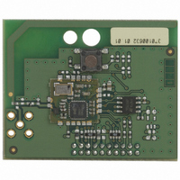
... ZM2120C ZM2120C- ZM3102N ZM3106C ZM3120C ZM3120C-EW Table 7 Z-Wave Module Selection Guide Zensys BOM P 908.42MHz 370100620 370100660 370100632 370100630 370100760 370100850 370100801 370100800 Table 8 Z-Wave Module BOM P/N Z-Wave API’S and Z-Wave Module Selection 2007-03-16 HW Options ANZ HK 921.42MHz 919.82MHz 370100830 370100830 ...
Page 16
INS10027-6 APPENDIX A NAMING OF 100 SERIES MODULES Explanation of the ZW0102 based Z-Wave Module naming. These modules are not recommended to be used in new products. Frequency 908.42MHz EU = 868.42MHz Z-Wave Module Zensys A/S Z-Wave Module ...
Page 17
INS10027-6 5 REFERENCES [1] Zensys, INS10247, Instruction, Z-Wave ZW0102/ZW0201/ZW0301 Appl. Prg. Guide v5.00 (Beta1) [2] Zensys, INS10244, Instruction, Z-Wave Node Type Overview and Network Installation Guide [3] Zensys, DSH10560, Datasheet, ZW0201 With Developers Kit v5.0x [4] Zensys, DSH10717, Datasheet, ZW0301 ...