EVAL-433-KH2 Linx Technologies Inc, EVAL-433-KH2 Datasheet - Page 2
EVAL-433-KH2
Manufacturer Part Number
EVAL-433-KH2
Description
KIT BASIC EVAL 433MHZ KH2 SERIES
Manufacturer
Linx Technologies Inc
Series
KH2r
Type
Transmitter, Receiverr
Datasheet
1.EVAL-315-KH2.pdf
(5 pages)
Specifications of EVAL-433-KH2
Frequency
433MHz
Product
RF Development Tools
Maximum Frequency
433.92 MHz
Supply Voltage (max)
3 V
Lead Free Status / RoHS Status
Lead free / RoHS Compliant
For Use With/related Products
KH2 Series RF Modules - 433MHz, Linx OEM Modules
Lead Free Status / Rohs Status
Lead free / RoHS Compliant


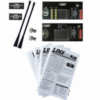
KH2 TRANSMITTER EVALUATION BOARD
KH2 RECEIVER EVALUATION BOARD
Page 2
1.
2.
3.
4.
5.
6.
7.
8.
9.
1.
2.
3.
4.
5.
6.
7.
8.
1
2
1
Battery - 3VDC (use a CR2032-style battery only)
Power Switch
Momentary Pushbutton - S0 (D0)
Momentary Pushbutton - S1 (D1)
Continuous Transmit Switches
Prototyping Area
Reverse-Polarity SMA Antenna Connector
KH2 Series Transmitter Module
10-Position Address DIP Switch
Battery - 3VDC (use 2 AAA style batteries only)
Power Switch
Buzzer - D0
LED - D1
Prototyping Area
KH2 Series Receiver Module
Reverse-Polarity SMA Antenna Connector
10-Position Address DIP Switch
3
5
2
4
3
5
6
4
6
8
7
8
9
7
THEORY OF OPERATION
USING THE KIT
DEVELOPMENT USING THE PROTOTYPING AREA
TRANSMITTER EVALUATION BOARD
RECEIVER EVALUATION BOARD
The transmitter board is powered by an on-board 3V CR2032 lithium battery. It
has eight SPST pushbutton switches, the state of which are encoded into a data
stream by the module. If a switch is closed, the module will capture the settings
of the 10-position DIP switch address bits and pushbutton states for encoding
and transmission. The transmitter will transmit continuously when any switch is
closed or when Transmit Enable (TE) is pulled high. This board has a prototyping
area with all of the transmitter lines brought out to a header for easy access by
external circuitry.
The receiver board is powered by two AAA batteries. The KH2 Series receiver
exhibits a sensitivity of greater than -112dBm, so under optimum line-of-sight
conditions, the transmitter / receiver link can operate over distances of up to
3,000 feet. The data recovered by the KH2 Series receiver is internally decoded.
If the settings of the 10-position DIP switch on the receiver board match the
address setting of the transmitter board, the data lines are updated to match the
state of the data lines (or pushbuttons) on the transmitter board. To demonstrate
this, one data line is used to drive a LED while another is used to activate a
buzzer. Switching transistors are used as drive buffers because the KH2 receiver
cannot directly source the current necessary to operate these devices. This
board has a prototyping area with all of the receiver lines brought out to a header
for easy access by external circuitry.
Using the kit is straightforward. Simply attach the antennas, turn on the power,
and press one or both of the buttons on the transmitter board. When S0 is
pressed, the buzzer will sound; when S1 is pressed, the LED will turn on.
In addition to their evaluation functions, the boards may also be used for actual
product development. They feature a prototyping area to facilitate the addition of
application-specific circuitry. This area has a connection to V
ground at the bottom that can be used to power the added circuitry.
NOTE: The CR2032-style battery on the transmitter board has very low current capacity,
with only about 3mA available for external circuitry. If added circuitry requires a higher
current, the battery must be removed and the board powered from an external source.
The holes are plated and set at 0.100” on center with a 0.040” diameter, making
it easy to add most industry-standard SIP and DIP packages to the board.
On the transmitter board, the data lines and the TE line from the encoder have
been wired out to a header on the right side of the prototyping area. On the
receiver board, the data lines from the decoder plus the PDN, and DATA lines
from the receiver have been wired out. This allows for easy access to connect
external circuitry to the modules, the encoder, and the decoder. Data line D0 is
connected to the buzzer and D1 is connected to the LED.
CC
at the top and
Page 3
Related parts for EVAL-433-KH2
Image
Part Number
Description
Manufacturer
Datasheet
Request
R

Part Number:
Description:
KIT BASIC EVAL 433MHZ LC SERIES
Manufacturer:
Linx Technologies Inc

Part Number:
Description:
KIT BASIC EVAL 433MHZ LR SERIES
Manufacturer:
Linx Technologies Inc
Datasheet:

Part Number:
Description:
KIT EVAL KEYFOB 433 MHZ 5 BUTTON
Manufacturer:
Linx Technologies Inc
Datasheet:

Part Number:
Description:
KIT BASIC EVAL 433MHZ KH SERIES
Manufacturer:
Linx Technologies Inc
Datasheet:

Part Number:
Description:
KIT EVAL FOR HHLR 433MHZ XMITTER
Manufacturer:
Linx Technologies Inc
Datasheet:

Part Number:
Description:
KIT EVAL FOR HHCP 433MHZ XMITTER
Manufacturer:
Linx Technologies Inc
Datasheet:

Part Number:
Description:
KIT EVAL FOR LT SERIES 433MHZ
Manufacturer:
Linx Technologies Inc
Datasheet:

Part Number:
Description:
KIT BASIC EVAL 433MHZ LC SERIES
Manufacturer:
Linx Technologies Inc
Datasheet:

Part Number:
Description:
RF Modules & Development Tools 3 Button Keyfob Eval Sys 433MHz
Manufacturer:
Linx Technologies Inc
Datasheet:
Part Number:
Description:
RF Modules & Development Tools 1 Button Keyfob Eval Sys 433MHz
Manufacturer:
Linx Technologies Inc
Datasheet:

Part Number:
Description:
MODULE USB LOW SPEED
Manufacturer:
Linx Technologies Inc
Datasheet:

Part Number:
Description:
IC TRANSCODER MT BI-DIR 20-SSOP
Manufacturer:
Linx Technologies Inc
Datasheet:

Part Number:
Description:
IC ENCODER LOW SECURITY 8DIP
Manufacturer:
Linx Technologies Inc
Datasheet:

Part Number:
Description:
IC DECODER MS SERIES 20-SSOP
Manufacturer:
Linx Technologies Inc
Datasheet:
Part Number:
Description:
IC ENCODER MS SERIES 20-SSOP
Manufacturer:
Linx Technologies Inc
Datasheet: