AC164105 Microchip Technology, AC164105 Datasheet
AC164105
Specifications of AC164105


Related parts for AC164105

AC164105 Summary of contents
Page 1
... Microchip Technology Inc. Development Kit 1 User’s Guide Preliminary ™ rfPIC DS70093A ...
Page 2
... Serialized Quick Turn Programming (SQTP service mark of Microchip Technology Incorporated in the U.S.A. All other trademarks mentioned herein are property of their respective companies. © 2003, Microchip Technology Incorporated, Printed in the U.S.A., All Rights Reserved. Printed on recycled paper. Microchip received QS-9000 quality system ...
Page 3
... Highlights ...................................................................................................... 13 3.3 rfRXD0420 Description ................................................................................. 14 3.4 rfRXD0420 Schematic .................................................................................. 15 3.5 PCB Layout .................................................................................................. 16 3.6 Gerber Files .................................................................................................. 16 3.7 rfRXD0420 Receiver Module Bill-of-Materials .............................................. 17 3.8 Third Party Component Suppliers ................................................................. 18 © 2003 Microchip Technology Inc. rfPIC™ Development Kit 1 Table of Contents Preliminary User’s Guide DS70093A-page iii ...
Page 4
... Third Party Component Suppliers ................................................................ 26 Chapter 5. Troubleshooting 5.1 Introduction ................................................................................................... 27 5.2 Frequently Asked Questions ........................................................................ 27 5.2.1 Devices on the PICkit™ Starter Kit Have No Power? ................... 27 5.2.2 Programmer Not Found ................................................................. 28 5.2.3 Insert Device .................................................................................. 28 5.2.4 Checksum Verify Failed ................................................................. 29 Worldwide Sales and Service .....................................................................................32 DS70093A-page iv Preliminary © 2003 Microchip Technology Inc. ...
Page 5
... Development Kit 1 and steps on how to resolve them. • Worldwide Sales and Service – A list of Microchip sales and service locations and telephone numbers worldwide. © 2003 Microchip Technology Inc. rfPIC™ Development Kit 1 User’s Guide Preface Preliminary ...
Page 6
... Preliminary Examples #define START c:\autoexec.bat <label>, <exp> MPASMWIN [main.asm] errorlevel {0|1} " " filename list " [ list_option..., " " list_option ] 0xFFFF, 0x007A char isascii (char, ch); File > Save OK, Cancel <Tab>, <Ctrl-C> ® MPLAB IDE User’s Guide © 2003 Microchip Technology Inc. ...
Page 7
... THE MICROCHIP INTERNET WEB SITE Microchip provides easy access to our documentation and on-line support through our World Wide Web Site at www.microchip.com. You can download files from the web site or from our FTP site at ftp://ftp.microchip.com © 2003 Microchip Technology Inc. ® Manuals Preliminary ...
Page 8
... LIB30 librarians. ® ICD and MPLAB ICD 2. ® IDE, the Windows ™ simulator, MPLAB IDE Project Manager and general editing ® II device programmer and PICSTART Preliminary ® C30 C Compilers; ® LINK30 linkers; ® Integrated ® Plus development © 2003 Microchip Technology Inc. ...
Page 9
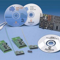
... Development Kit 1 CD-ROM 8. PICkit 1 FLASH Starter Kit Printed Circuit Board 9. USB Cable 10. PICkit™ 1 FLASH Starter Kit CD-ROM ® 11. MPLAB © 2003 Microchip Technology Inc. rfPIC™ Development Kit 1 ® microcontrollers with UHF ASK/FSK IDE CD-ROM Preliminary User’s Guide ...
Page 10
... Frequency 315 MHz 433.92 MHz FIGURE 1-1: USB Cable DS70093A-page 6 Antenna Length 9-3/8” 6-3/4” rfPIC RECEIVER DEMONSTRATION Wire Antenna Expansion Header (J3) LED D1 Preliminary rfRXD Receiver Module LED D0 Insert PIC16F676 PICkit™ FLASH Starter Kit © 2003 Microchip Technology Inc. ...
Page 11
... The HEX files can be programmed into the rfPIC transmitter and receiver modules using the PICkit 1 FLASH Starter kit. The source code can be modified and compiled using the MPLAB software and the resulting HEX files programmed in the same manner. © 2003 Microchip Technology Inc. rfPIC TRANSMITTER DEMONSTRATION Jumper ® ...
Page 12
... Development Kit 1 User’s Guide NOTES: DS70093A-page 8 Preliminary © 2003 Microchip Technology Inc. ...
Page 13
... Chapter 4 of this User’s Guide. The receiver module demonstration programs are programmed into the PIC16F676 by following the steps outlined in the PICkit™ 1 FLASH Starter Kit User’s Guide. © 2003 Microchip Technology Inc. rfPIC™ Development Kit 1 – ...
Page 14
... GP0. Pressing push button GP4 lights LEDs D0-D7 with the upper 8-bit value read from A/D channel 1 connected to potentiometer GP1. The protocol is a simplified K products. This receive code was adapted from Microchip Technology application note AN740. The 10-bit analog value is placed into the 16-bit counter field of the simplified K protocol ...
Page 15
... PICSTART II programmer. Step 2: Remove the PICkit 1 FLASH Kit programmed PIC16C745 from socket U1. Insert the PIC16C745 programmed with pres_pal.hex into socket U1. © 2003 Microchip Technology Inc. Demonstration Programs APPROXIMATE SIGNAL RATES NRZ bps (0-100% GP1) 52.6-3.64 kbps 3 ...
Page 16
... Use this template to program the PIC12F629 or PIC12F675 8-pin FLASH PICmicro MCU or the rfPIC12F675K/675F/675H PICmicro MCU with UHF ASK/FSK transmitter devices. PIC16F630-676 Assembly Language Programming Template.asm Use this template to program the PIC16F630 or PIC16F676 14-pin FLASH PICmicro microcontroller. DS70093A-page 12 Preliminary ® © 2003 Microchip Technology Inc. ...
Page 17
... Receiver Module Schematic • PCB Layout • Gerber Files • Bill-of-Materials • Third Party Component Suppliers © 2003 Microchip Technology Inc. rfPIC™ Development Kit 1 RECEIVER MODULE ORDERING INFORMATION Order Number Single AC164104 AC164103 Preliminary User’s Guide 5 Pack AC164106 AC164105 DS70093A-page 13 ...
Page 18
... PCB and ground pad on the back side of the PCB. DS70093A-page 14 rfRXD0420 RECEIVER MODULE rfRXD0420 RECEIVER MODULE PINOUT Description No Connection Receive Data In No Connection Power: 2.5-5.5 VDC Ground Antenna Connection λ (meters (Hertz speed of light (meters per second) Preliminary © 2003 Microchip Technology Inc. ...
Page 19
... SCHEMATIC Figure 3 detailed schematic of the rfRXD0420 module. FIGURE 3-2: rfRXD0420 RECEIVER MODULE © 2003 Microchip Technology Inc. rfRXD0420 Receiver Module OUT_OA IF1N OAN IF1P OAP SS V RSSI IN_MIX1 VSS OUT_LNA OUTP NC GAIN_LNA NC OUTN V SS Preliminary DS70093A-page 15 ...
Page 20
... The following figures illustrate the various layers of the rfRXD0420 receiver module printed circuit board. FIGURE 3-3: FIGURE 3-4: FIGURE 3-5: 3.6 GERBER FILES Gerber Files for the rfRXD0420 are available on the rfPIC Development Kit 1 CD-ROM. DS70093A-page 16 rfRXD0420 TOP SILK-SCREEN rfRXD0420 TOP COPPER rfRXD0420 BOTTOM COPPER Preliminary © 2003 Microchip Technology Inc. ...
Page 21
... RECEIVER MODULE BILL-OF-MATERIALS © 2003 Microchip Technology Inc. rfRXD0420 Receiver Module Preliminary DS70093A-page 17 ...
Page 22
... Wood Avenue South Iselin, NJ 08830 Phone: 1-732-906-4300 Fax: 1-732-603-5935 E-Mail: sales.usa@epcos.com Internet: http://www.usa.epcos.com Murata Electronics North America, Inc. Corporate Headquarters 2200 Lake Park Drive Smyrna, GA 30080-7604 Phone: 1-770-436-1300 Fax: 1-770-436-3030 Internet: http://www.murata-northamerica.com DS70093A-page 18 Preliminary © 2003 Microchip Technology Inc. ...
Page 23
... GP0 and GP1 • RF enable (RF • Data ASK (DATA • Optional 8-pin socket (U2) for In-Circuit Emulation (ICE) or inserting an 8-pin DIP package version of the PIC12F675. © 2003 Microchip Technology Inc. rfPIC™ Development Kit 1 TRANSMITTER MODULE ORDERING INFORMATION Frequency 315 MHz 433 ...
Page 24
... A detailed description of the rfPIC12F675K/675F/675H microcontroller with UHF ASK/FSK transmitter is provided in the data sheet, DS70091. A detailed description of the rfPIC12F675K/675 transmitter module antenna design is provided in the application note, AN868. DS70093A-page 20 ® ICE-2000 and ICD2. ® Plus or PRO MATE Preliminary ® ® II) or © 2003 Microchip Technology Inc. ...
Page 25
... Table 4-2 lists the pinout associated with the rfPIC12F675 module. TABLE 4-2: Pin 10, 11 FIGURE 4-2: USB Cable © 2003 Microchip Technology Inc. rfPIC12F675 Transmitter Module rfPIC12F675 TRANSMITTER MODULE rfPIC12F675 TRANSMITTER MODULE PINOUT Description GP5 GP4 GP3 No Connection GP0 GP1 GP2 No Connection Power: 2.0-5.5 VDC Ground ...
Page 26
... Development Kit 1 User’s Guide 4.4 rfPIC12F675 SCHEMATIC FIGURE 4-3: rfPIC12F675 TRANSMITTER MODULE DS70093A-page 22 Antenna Loop Preliminary © 2003 Microchip Technology Inc. ...
Page 27
... PCB LAYOUT The following diagrams show the various layers of the rfPIC12F675 transmitter module printed circuit board. FIGURE 4-4: FIGURE 4-5: © 2003 Microchip Technology Inc. rfPIC12F675 Transmitter Module rfPIC12F675 TRANSMITTER MODULE TOP SILK-SCREEN rfPIC12F675 TRANSMITTER MODULE TOP COPPER Preliminary DS70093A-page 23 ...
Page 28
... Development Kit 1 User’s Guide FIGURE 4-6: 4.6 GERBER FILES Gerber Files for the rfPIC12F675 transmitter module are available on the rfPIC Development Kit 1 CD-ROM. DS70093A-page 24 rfPIC12F675 TRANSMITTER MODULE BOTTOM COPPER Preliminary © 2003 Microchip Technology Inc. ...
Page 29
... TRANSMITTER MODULE BILL-OF-MATERIALS © 2003 Microchip Technology Inc. rfPIC12F675 Transmitter Module Preliminary DS70093A-page 25 ...
Page 30
... Development Kit 1 User’s Guide 4.8 THIRD PARTY COMPONENT SUPPLIERS Crystek Crystal Corporation 12730 Commonwealth Drive Fort Myers, FL 33913 Toll Free: 1-800-237-3061 Phone: 1-239-561-3311 Fax: 1-239-561-1025 E-mail: salesdept@crystek.com Internet: http://www.crystek.com DS70093A-page 26 Preliminary © 2003 Microchip Technology Inc. ...
Page 31
... Make sure that the DEVICE POWER checkbox (Figure 5-1) on the PICkit GUI is checked. This feature allows you to control the device under test power from the PICkit GUI. FIGURE 5-1: © 2003 Microchip Technology Inc. rfPIC™ Development Kit 1 DEVICE POWER CONTROL Preliminary User’ ...
Page 32
... I am trying to program the transmitter module and I am getting an “Insert Device” status message (see Figure 5-3). Answer: Check that the Pwr Sel jumper the PICkit Starter Kit position (pins 1 and 2 jumpered). FIGURE 5-3: DS70093A-page 28 PROGRAMMER NOT FOUND STATUS MESSAGE INSERT DEVICE STATUS MESSAGE Preliminary © 2003 Microchip Technology Inc. ...
Page 33
... I am trying to program the transmitter module and I am getting an “Checksum Verify Failed” status message (Figure 5-4). Answer: Check that the Pwr Sel jumper the PICkit Starter Kit position (pins 1 and 2 jumpered). FIGURE 5-4: © 2003 Microchip Technology Inc. Troubleshooting CHECKSUM VERIFY FAILED STATUS MESSAGE Preliminary DS70093A-page 29 ...
Page 34
... Development Kit 1 User’s Guide NOTES: DS70093A-page 30 Preliminary © 2003 Microchip Technology Inc. ...
Page 35
... NOTES: © 2003 Microchip Technology Inc. Troubleshooting Preliminary DS70093A-page 31 ...
Page 36
... Korea Microchip Technology Korea 168-1, Youngbo Bldg. 3 Floor Samsung-Dong, Kangnam-Ku Seoul, Korea 135-882 Tel: 82-2-554-7200 Fax: 82-2-558-5934 Singapore Microchip Technology Singapore Pte Ltd. 200 Middle Road #07-02 Prime Centre Singapore, 188980 Tel: 65-6334-8870 Fax: 65-6334-8850 Taiwan Microchip Technology (Barbados) Inc., Taiwan Branch 11F-3, No ...