ATAB5428-4-WB Atmel, ATAB5428-4-WB Datasheet - Page 20
ATAB5428-4-WB
Manufacturer Part Number
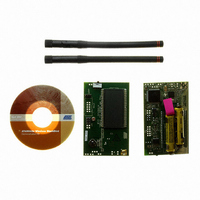
ATAB5428-4-WB
Description
KIT DEMO 434MHZ BLACKBIRD
Manufacturer
Atmel
Series
Smart RFr
Type
Transceiver, UHFr
Specifications of ATAB5428-4-WB
Frequency
434MHz
Maximum Frequency
434 MHz
Output Power
0 dBm to 10 dBm
Supply Voltage (max)
6 V
Supply Voltage (min)
3 V
Supply Current
21 mA
Maximum Operating Temperature
+ 85 C
Board Size
2 in x 3.5 in
Minimum Operating Temperature
- 40 C
Product
RF Modules
For Use With/related Products
ATA5428
Lead Free Status / RoHS Status
Lead free / RoHS Compliant
Other names
ATAB-5428-4-WB


2.3.6.8
2.3.6.9
2.3.6.10 RF MODULE
ATAB542x-x-WB User Guide
CLK OUT
TIME
SELECT
Outputs a square wave on JTAG-header pin #5
P - activates output
L - goes to SYSTEM SET-UP
U,D - scrolls through menu (PWR DWN, CHANNEL ADJUST…)
Note:
Displays day/date/time information
P - displays information
L - goes to SYSTEM SET-UP
U,D - scrolls through menu (PWR DWN, CHANNEL ADJUST…)
Loads pre-set register data for each RF frequency
P -accesses menu items
L - goes to SYSTEM SET-UP
U,D - scrolls through menu (PWR DWN, CHANNEL ADJUST…)
VCC 3 - the voltage source output is on A/D channel 3
CLK OUT and AVR logo - indicates output is activated
P,L,R,U,D - goes to SYSTEM SETUP
5429 – 915MHZ - selects pre-set data for 915MHz
5423 – 315MHZ - selects pre-set data for 315MHz
5425 – 345MHZ - selects pre-set data for 345MHz
L,R,U,D - goes to SYSTEM SETUP
P (again) - goes to LGHT 2
P - displays the hex value out of the A/D converter
L,R,U,D - goes to SYSTEM SETUP
P (again) - goes to VCC 3
P,L,R,U,D - deactivates clock output and goes to SYSTEM SETUP
P - selects 915MHz data is loaded, and then goes to SYSTEM SET-UP
L - goes to SYSTEM SET-UP
U,D - scrolls through menu (5423 – 315MHZ, 5425 – 345MHZ,…)
P - selects 315MHz data is loaded, and then goes to SYSTEM SET-UP
L - goes to SYSTEM SET-UP
U,D - scrolls through menu (5423 – 315MHZ, 5425 – 345MHZ,…)
P - selects 345MHz data is loaded, and then goes to SYSTEM SET-UP
L - goes to SYSTEM SET-UP
this square wave is 10 CPU-cycles high, then 10 CPU-cycles low, repeating.
L,R,U,D - goes to SYSTEM SET-UP
Operating the Transceivers
5219A–WIRE–04/07
2-15
Related parts for ATAB5428-4-WB
Image
Part Number
Description
Manufacturer
Datasheet
Request
R


Part Number:
Description:
KIT DEMO 868MHZ BLACKBIRD
Manufacturer:
Atmel
Datasheet:

Part Number:
Description:
BOARD BASESTATN UHF RCVR 433MHZ
Manufacturer:
Atmel
Datasheet:
Part Number:
Description:
BOARD BASESTATN UHF RCVR 868MHZ
Manufacturer:
Atmel
Datasheet:

Part Number:
Description:
DEV KIT FOR AVR/AVR32
Manufacturer:
Atmel
Datasheet:

Part Number:
Description:
INTERVAL AND WIPE/WASH WIPER CONTROL IC WITH DELAY
Manufacturer:
ATMEL Corporation
Datasheet:
Part Number:
Description:
Low-Voltage Voice-Switched IC for Hands-Free Operation
Manufacturer:
ATMEL Corporation
Datasheet:
Part Number:
Description:
MONOLITHIC INTEGRATED FEATUREPHONE CIRCUIT
Manufacturer:
ATMEL Corporation
Datasheet:
Part Number:
Description:
AM-FM Receiver IC U4255BM-M
Manufacturer:
ATMEL Corporation
Datasheet:
Part Number:
Description:
Monolithic Integrated Feature Phone Circuit
Manufacturer:
ATMEL Corporation
Datasheet:
Part Number:
Description:
Multistandard Video-IF and Quasi Parallel Sound Processing
Manufacturer:
ATMEL Corporation
Datasheet:
Part Number:
Description:
High-performance EE PLD
Manufacturer:
ATMEL Corporation
Datasheet: