ATAKSTK511-8 Atmel, ATAKSTK511-8 Datasheet - Page 35
ATAKSTK511-8
Manufacturer Part Number
ATAKSTK511-8
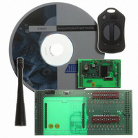
Description
KIT RF MODULE 868MHZ FOR STK500
Manufacturer
Atmel
Series
SmartRF®r
Type
Transmitter, Receiver, ASK, FSKr
Specifications of ATAKSTK511-8
Frequency
868MHz
Wireless Frequency
868 MHz
For Use With/related Products
ATSTK500
Lead Free Status / RoHS Status
Contains lead / RoHS non-compliant


3.9.1
3.10
AVR STK500 User Guide
Signal Descriptions
Prog Ctrl and
Prog Data
Headers
The signals AUXI1, AUXI0, AUXO1, and AUXO0 are intended for future use. Do not
connect these signals to your application.
The DATA[7:0] and CT[7:1] signals are also found on the Prog Data and Prog Ctrl con-
nectors. These signals and connectors are explained in Section 3.10 on page 3-25.
The BSEL2 signal is the same as that found on the BSEL2 jumper. This jumper is
explained in Section 3.8.5 on page 3-22.
The SI, SO, SCK, and CS signals are connected to the DataFlash. Use of the DataFlash
is described in Section 3.6 on page 3-6.
NC means that this pin is not connected.
The remaining signals are equal to those found on the PORT connectors, explained in
Section 3.4 on page 3-3.
Note:
The Prog Ctrl and Prog Data headers are used for High-voltage Programming of the tar-
get AVR device. The placement of the headers is shown in Figure 3-33. During parallel
High-voltage Programming, the Prog Ctrl signals are routed to PORTD of the target
device. The Prog Data signals are routed to PORTB. See Section 3.7.2 on page 3-11 for
a complete description of High-voltage Programming. The pinouts of the Prog Ctrl and
Prog Data headers are shown in Figure 3-36 and Figure 3-37. For more information
about High-voltage Programming of AVR devices, see the programming section of each
AVR datasheet.
Note:
Figure 3-36. Prog Ctrl Header Pinout
The Prog Ctrl signals are normally used for the control signals when parallel High-
voltage Programming an AVR device.
Note:
DATA, CT, and AUX signals are based on 5V CMOS logic. No voltage conver-
sion to adapt to VTG is done on these signals.
Prog Ctrl and Data connectors are connected directly to the master microcon-
troller without level converters. This means that these signals are always 5V
logic.
All Prog Ctrl signals are based on 5V CMOS logic. No voltage conversion to
adapt to VTG is done on these signals.
(BS1)CT4
(XA1)CT6
(OE)CT2
GND
NC
1 2
CT1(RDY/BSY)
CT3(/WR)
CT5(XA0)
CT7(PAGEL)
NC
Hardware Description
1925C–AVR–3/03
3-25
Related parts for ATAKSTK511-8
Image
Part Number
Description
Manufacturer
Datasheet
Request
R

Part Number:
Description:
DEV KIT FOR AVR/AVR32
Manufacturer:
Atmel
Datasheet:

Part Number:
Description:
INTERVAL AND WIPE/WASH WIPER CONTROL IC WITH DELAY
Manufacturer:
ATMEL Corporation
Datasheet:
Part Number:
Description:
Low-Voltage Voice-Switched IC for Hands-Free Operation
Manufacturer:
ATMEL Corporation
Datasheet:
Part Number:
Description:
MONOLITHIC INTEGRATED FEATUREPHONE CIRCUIT
Manufacturer:
ATMEL Corporation
Datasheet:
Part Number:
Description:
AM-FM Receiver IC U4255BM-M
Manufacturer:
ATMEL Corporation
Datasheet:
Part Number:
Description:
Monolithic Integrated Feature Phone Circuit
Manufacturer:
ATMEL Corporation
Datasheet:
Part Number:
Description:
Multistandard Video-IF and Quasi Parallel Sound Processing
Manufacturer:
ATMEL Corporation
Datasheet:
Part Number:
Description:
High-performance EE PLD
Manufacturer:
ATMEL Corporation
Datasheet:
Part Number:
Description:
8-bit Flash Microcontroller
Manufacturer:
ATMEL Corporation
Datasheet:
Part Number:
Description:
2-Wire Serial EEPROM
Manufacturer:
ATMEL Corporation
Datasheet: