HRF-AT4521-E Honeywell Microelectronics & Precision Sensors, HRF-AT4521-E Datasheet - Page 3
HRF-AT4521-E
Manufacturer Part Number
HRF-AT4521-E
Description
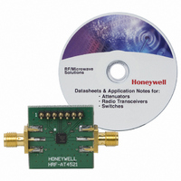
BOARD EVALUATION FOR HRF-AT4521
Manufacturer
Honeywell Microelectronics & Precision Sensors
Type
Attenuatorr
Datasheet
1.HRF-AT4521-AU.pdf
(7 pages)
Specifications of HRF-AT4521-E
Frequency
0Hz ~ 2.5GHz
For Use With/related Products
HRF-AT4521
Lead Free Status / RoHS Status
Lead free / RoHS Compliant
Other names
342-1047


HRF- AT4521
PIN CONFIGURATIONS
Note: Bottom ground plate must be grounded for proper RF performance.
SERIAL DATA LOAD
Serial data is shifted into the register on the rising edge of clock, MSB first. The state of “OE” will not affect the shifting of
data. The rising edge of the “OE” signal will be the clock for the transfer of shifted data. Latched new data occurs one
prop delay after the rising edge of “OE”. See the Electrical Spec Table for AC parameters.
TRUTH TABLE
Operation: Data on serial input D is clocked into internal registers on the low to high transition of the Clock signal (CK).
The register output is enabled when Output Enable (OE) is in the low state.
www.honeywell.com/microwave
Pin
1
2
3
4
5
6
7
8
S4
0
0
0
0
0
1
1
Function
RF INPUT
GROUND
GROUND
GROUND
GROUND
GROUND
GROUND
VDD
S3
0
0
0
0
1
0
1
Pin
11
12
13
14
15
16
10
9
S2
0
0
0
1
0
0
1
RF OUTPUT
Function
GROUND
GROUND
GROUND
DATA
VSS
CLK
OE
S1
0
0
1
0
0
0
1
S0
0
1
0
0
0
0
1
Reference Input
Output
16 dB
31 dB
"0" = CMOS Low, "1" = CMOS High.
1 dB
2 dB
4 dB
8 dB
3
Related parts for HRF-AT4521-E
Image
Part Number
Description
Manufacturer
Datasheet
Request
R

Part Number:
Description:
Radio On A Chip 300
Manufacturer:
Honeywell International's Solid State Electronics Center (SSEC)
Datasheet:
Part Number:
Description:
Radio On A Chip 300 - 928 MHz FSK Transceiver Frequency Agile With SPI Bus Interface
Manufacturer:
HONEYWELL [Honeywell Solid State Electronics Center]
Datasheet:
Part Number:
Description:
Radio On A Chip 860-928 MHz Frequency Agile With SPI Bus Interface
Manufacturer:
ETC1 [List of Unclassifed Manufacturers]
Datasheet:

Part Number:
Description:
MAGNETIC SENSORS
Manufacturer:
Honeywell Microelectronics & Precision Sensors

Part Number:
Description:
MAGNETIC SENSORS
Manufacturer:
Honeywell Microelectronics & Precision Sensors

Part Number:
Description:
MAGNETIC SENSORS
Manufacturer:
Honeywell Microelectronics & Precision Sensors
Part Number:
Description:
MAGNETIC SENSORS
Manufacturer:
Honeywell Microelectronics & Precision Sensors
Part Number:
Description:
MAGNETIC SENSORS
Manufacturer:
Honeywell Microelectronics & Precision Sensors
Datasheet:
Part Number:
Description:
MAGNETIC SENSORS
Manufacturer:
Honeywell Microelectronics & Precision Sensors

Part Number:
Description:
MAGNETIC SENSORS
Manufacturer:
Honeywell Microelectronics & Precision Sensors
Datasheet:

Part Number:
Description:
SENSOR LINEAR MAGN 1 AXIS 8-SIP
Manufacturer:
Honeywell Microelectronics & Precision Sensors
Datasheet:

Part Number:
Description:
SENSOR MAGN 2 AXIS 10-MSOP
Manufacturer:
Honeywell Microelectronics & Precision Sensors
Datasheet:

Part Number:
Description:
Magnetic Sensor
Manufacturer:
Honeywell Microelectronics & Precision Sensors
Datasheet:

Part Number:
Description:
Magnetic Sensor
Manufacturer:
Honeywell Microelectronics & Precision Sensors
Datasheet:

Part Number:
Description:
IC, MAGNETO RESISTIVE SENSOR, LCC-16
Manufacturer:
Honeywell Microelectronics & Precision Sensors
Datasheet: