RF2312PCK-50 OHM RFMD, RF2312PCK-50 OHM Datasheet - Page 6
RF2312PCK-50 OHM
Manufacturer Part Number
RF2312PCK-50 OHM
Description
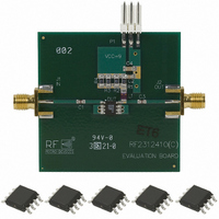
KIT EVAL FOR RF2312 50OHM
Manufacturer
RFMD
Type
Amplifierr
Datasheet
1.RF2312TR7.pdf
(16 pages)
Specifications of RF2312PCK-50 OHM
Frequency
0Hz ~ 2.5GHz
For Use With/related Products
RF2312 50 Ohm
Lead Free Status / RoHS Status
Lead free / RoHS Compliant
Other names
689-1032


3-6
RF2312
RF IN
R5 is used to maintain the correct bias level at higher supply voltages and is also required in this configuration. The RC network of R2
and C3 should be kept physically as short as possible. R2 can be adjusted as required to improve the impedance matching. R6 and
R7 reduce the typical gain by increasing the emitter resistance. L1 should be at least 200 Ω reactive at the lowest operating
frequency. C1 and C2 should be less than 10 Ω at the lowest operating frequency. C4 and C5 improve gain flatness.
RF IN
NOTE 1:
Optional resistor R
increase output capability or linearity for signals with high crest factors.
220 pF
C1
TBD
C4
1 - 2 kΩ
10 nF
R5
7.5 Ω
R6
S
can be used to maintain the correct bias level at higher supply voltages. This is used to
1 - 2 kΩ
5MHz to 50MHz Reverse Path
R
S
Application Schematic
Application Schematic
1
2
3
4
1
2
3
4
10dB Gain
10 nF
C3
470 Ω
R2
8
7
6
5
8
7
6
5
10 μH
30 Ω
7.5 Ω
R7
100 nF
10 nF
V
V
CC
CC
= 9 - 12 V
R1 = 21 - 30 Ω
330 nH
TBD
220 pF
C5
100 nF
L1
C2
RF OUT
Rev C6 051025
RF OUT
Related parts for RF2312PCK-50 OHM
Image
Part Number
Description
Manufacturer
Datasheet
Request
R

Part Number:
Description:
IC AMP HBT GAAS CATV 8-SOIC
Manufacturer:
RFMD
Datasheet:

Part Number:
Description:
IC AMP MMIC GAAS 12GHZ 4-MICROX
Manufacturer:
RFMD
Datasheet:

Part Number:
Description:
IC AMP 3V LOW-NOISE SOT23-6
Manufacturer:
RFMD
Datasheet:

Part Number:
Description:
KIT EVAL FOR NBB-310
Manufacturer:
RFMD
Datasheet:
Part Number:
Description:
IC AMPLIFIER MMIC LNA 8-QFN
Manufacturer:
RFMD
Datasheet:
Part Number:
Description:
IC AMP MMIC GAAS 4GHZ 4-MICROX
Manufacturer:
RFMD
Datasheet:
Part Number:
Description:
IC SWITCH 10W PHEMT SPDT 12QFN
Manufacturer:
RFMD
Datasheet:
Part Number:
Description:
IC QUADRATURE MODULATOR 16-SOIC
Manufacturer:
RFMD
Datasheet:
Part Number:
Description:
100MHZ TO 4000MHZ, GAAS PHEMT MMIC LOW NOISE AMPLIFIERS
Manufacturer:
RFMD
Part Number:
Description:
KIT EVAL FOR RF2336
Manufacturer:
RFMD
Datasheet:


Part Number:
Description:
IC AMP WLAN/LNA DVR 3V SOT23-5
Manufacturer:
RFMD
Datasheet:

Part Number:
Description:
IC AMP HBT GAAS LNA BYPASS 8-QFN
Manufacturer:
RFMD
Datasheet:

Part Number:
Description:
IC AMP MMIC GAAS 10GHZ 4-MICROX
Manufacturer:
RFMD
Datasheet: