STEVAL-SPBT2ATV1 STMicroelectronics, STEVAL-SPBT2ATV1 Datasheet
STEVAL-SPBT2ATV1
Specifications of STEVAL-SPBT2ATV1


Related parts for STEVAL-SPBT2ATV1


STEVAL-SPBT2ATV1 Summary of contents
Page 1
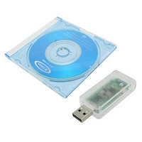
... The USB connector is used to connect the dongle with a PC, to access the Bluetooth module and to supply the dongle. The STEVAL-SPBT2ATV2 is a board with downloaded FW which enables the user to create a Bluetooth link with simple AT commands easy solution to test and operate with the SPBT2532C2.AT module. The features are: ■ ...
Page 2
Contents Contents 1 Qualification . . . . . . . . . . . . . . . . . . . . . . . . . . . . . . . . . . . . ...
Page 3
... AN3189 List of figures Figure 1. STEVAL-SPBT2ATV2 dongle Figure 2. Available pads . . . . . . . . . . . . . . . . . . . . . . . . . . . . . . . . . . . . . . . . . . . . . . . . . . . . . . . . . . . 6 Figure 3. Reset switch . . . . . . . . . . . . . . . . . . . . . . . . . . . . . . . . . . . . . . . . . . . . . . . . . . . . . . . . . . . . . 7 Figure 4. Dongle component layout . . . . . . . . . . . . . . . . . . . . . . . . . . . . . . . . . . . . . . . . . . . . . . . . . . . 8 Figure 5. Dongle electrical drawing . . . . . . . . . . . . . . . . . . . . . . . . . . . . . . . . . . . . . . . . . . . . . . . . . . . 9 Figure 6. USB drive installation first and second step . . . . . . . . . . . . . . . . . . . . . . . . . . . . . . . . . . . . 10 Figure 7. Wizard installation first step . . . . . . . . . . . . . . . . . . . . . . . . . . . . . . . . . . . . . . . . . . . . . . . . 10 Figure 8. Wizard installation second step . . . . . . . . . . . . . . . . . . . . . . . . . . . . . . . . . . . . . . . . . . . . . 11 Figure 9. Wizard installation third step . . . . . . . . . . . . . . . . . . . . . . . . . . . . . . . . . . . . . . . . . . . . . . . . 11 Figure 10 ...
Page 4
Qualification 1 Qualification Bluetooth module SPBT2532C2.AT is CE, BQB qualified, and FCC compliant. CE Registration: 0307-ARAJ00079 Measurements have been performed in accordance with (report available on request): ● EN 300 328 V 1.7.1 (2004-11): “electromagnetic compatibility and radio spectrum Matters ...
Page 5
AN3189 2 Demonstration board usage limitation The dongle based on the SPBT2532C2.AT module is not qualified pure demonstration tool only for evaluation purpose and not a product in itself. Demonstration board usage limitation Doc ID 17332 Rev ...
Page 6
Recommended operating conditions 3 Recommended operating conditions Table 1. Recommended operating conditions Symbol V DD Top Operating case temperature range 4 I/O connections 4.1 PAD description Other than the USB plug, some pads are also available. In fact TP1 and ...
Page 7
AN3189 Table 2. Pad connections Pads TP 4.2 Reset switch A reset switch SW1 is present on the dongle. When SW1 is pushed SPBT2532C2.AT is forced to reset. The following prompt is displayed on the screen: ● AT-AB - command ...
Page 8
Dongle layout 5 Dongle layout Figure 4. Dongle component layout 8/30 Doc ID 17332 Rev 2 AN3189 ...
Page 9
AN3189 6 Dongle schematic Figure 5. Dongle electrical drawing Doc ID 17332 Rev 2 Dongle schematic 9/30 ...
Page 10
... If the USB driver is not present on the PC you need to apply a simple installation procedure as follows: ● Step 1: Simply plug the STEVAL-SPBT2ATV2 into any available USB port. The computer responds with the following two messages: Figure 6. USB drive installation first and second step ● ...
Page 11
... AN3189 Figure 8. Wizard installation second step Now the STEVAL-SPBT2ATV2 USB to UART controller and virtual COM port driver is installed. ● Step 3: The “Found New Hardware Wizard” now opens again in order to install the USB device driver. Select Yes to locate the drivers from the Microsoft website. ...
Page 12
... Open the Windows device manager application to verify correct installation, and see which COM port has been assigned to the STEVAL-SPBT2ATV2 Bluetooth serial device. The STEVAL-SPBT2ATV2 is usually assigned the same virtual COM port each time it is inserted (unless there are other virtual COM devices altering port assignments). ...
Page 13
AN3189 Figure 12. Basic setup (Please refer to the SPBT2532C2.AT datasheet appendix C, for listing and meaning of the AT commands). 7.2.1 Startup Two dongles are needed to perform the connection. Each dongle has its own BD address. Suppose 0080e1f00001 ...
Page 14
Getting started Figure 13. Connection setup Set the connection port: Figure 14. Connection port setup and configure it: Figure 15. Port parameters 14/30 Doc ID 17332 Rev 2 AN3189 ...
Page 15
AN3189 with the following parameters: – Select the proper COM line (COM1, COM2……) – Set baud rate = 115000 (default baud rate of SPBT2532C2.AT module) – Set data bits= 8 – Set stop bits= 1 – Set parity= none – ...
Page 16
Getting started Figure 18. BDAddress dongle1, dongle2 7.2.2 Inquiry and available services Before establishing a connection, the dongle must know which Bluetooth devices are present and which services are offered. Each module has its own address which identifies the module ...
Page 17
AN3189 ● Service: To verify at the same time which kind of service is available use the command: AT+AB discovery [CoD] [profile] Response is: AT-AB Device [BD addr] [name consequence of a discovery command for SPP service issued ...
Page 18
Getting started In this case dongle1 is requesting a bonding with dongle2. Figure 21. Bonding dongle1, dongle2 ● Connection: Once the dongle knows the device present and the service offered, the command to setup connection is: – AT+AB SPPconnect [BD ...
Page 19
AN3189 If, for example, the user needs to change some parameters of a dongle it’s necessary to switch to -command mode-, giving the “escape command”. The escape command is a special sequence of characters followed by at least two seconds ...
Page 20
Getting started Now the two dongles can exchange data again. ● Disconnection: The SPPDisconnect command is used to terminate a connection with the remote device. – AT+AB SPPDisconnect If the disconnection is successful, the response is: – AT-AB SPPConnectionClosed SPPDisconnect ...
Page 21
AN3189 This command is stored inside the non-volatile memory and executed at power-on. In case dongle2 is already powered: Figure 26. Smart cable dongle1, dongle2 If dongle2 is not powered or not available, dongle1 automatically retries 5 times. Figure 27. ...
Page 22
Getting started Figure 28. Automatic connection dongle1, dongle2 ● Delete smart cable setup: The command to remove the SmartCableSetup is: – AT+AB DeleteSmartCable if the operation is successful the answer is: – AT-AB DeleteSmartCableDone To give the command the dongle ...
Page 23
AN3189 Figure 29. Change syntax dongle1 Note: Change reply prefix. 7.2.4 GPIO and LED On the dongle there are 4 LEDs connected to GPIO 1-4. Each LED can be switched on/off by driving the corresponding GPIO. GPIO must be configured ...
Page 24
Getting started Example: Figure 30. GPIO set dongle1 7.3 Point-to-point connection Modules with AT command firmware can only perform point-to-point connections. Only one connection can be activated at once. A module can be connected to several other modules, but it ...
Page 25
AN3189 Figure 31. Point-to-point connection In this case the following procedure must be used: ● C1 establishes the connection exchange data ● C1 disconnects from S1 using the command AT+AB SPPDisconnet ● C1 establishes the connection to ...
Page 26
USB driver installation Appendix A USB driver installation In a case where USB driver wizard installation fails, the dongle can be installed using the drive available on the silicon lab website at www.silabs.com/support/pages/support.aspx?ProductFamily=USB+to+UART&PartNumber =cp2102. Insert the dongle into a USB ...
Page 27
AN3189 Figure 34. Wizard installation 1 Figure 35. Wizard installation 2 Figure 36. Wizard installation 3 Doc ID 17332 Rev 2 USB driver installation 27/30 ...
Page 28
USB driver installation Figure 37. Wizard installation terminated Figure 38. Installation completed The USB driver installation is now complete. 28/30 Doc ID 17332 Rev 2 AN3189 ...
Page 29
... AN3189 8 Revision history Table 3. Document revision history Date 18-Jun-2010 04-Apr-2011 Revision 1 Initial release. Code of the board changed: from STEVAL-SPBT2ATV1 to 2 STEVAL-SPBT2ATV2 Doc ID 17332 Rev 2 Revision history Changes 29/30 ...
Page 30
... Information in this document is provided solely in connection with ST products. STMicroelectronics NV and its subsidiaries (“ST”) reserve the right to make changes, corrections, modifications or improvements, to this document, and the products and services described herein at any time, without notice. All ST products are sold pursuant to ST’s terms and conditions of sale. ...