DR-TRC103-915-DK RFM, DR-TRC103-915-DK Datasheet - Page 2
DR-TRC103-915-DK
Manufacturer Part Number
DR-TRC103-915-DK
Description
RFIC TRANCEIVER DEVELOPMENT KIT
Manufacturer
RFM
Type
Transceiver, SRRr
Datasheets
1.DR-TRC103-868-DK.pdf
(1 pages)
2.DR-TRC103-868-DK.pdf
(22 pages)
3.DR-TRC103-868-DK.pdf
(6 pages)
Specifications of DR-TRC103-915-DK
Frequency
902MHz ~ 928MHz
For Use With/related Products
TRC103-915
Lead Free Status / RoHS Status
Lead free / RoHS Compliant
Other names
583-1057


TX/RX/SLP Mode Select
Range Test Quick Start:
1- Insert AA batteries into battery case of both boards.
2- Turn on the boards by sliding the switch as indicated in Fig. 1 above. All LED’s will
3- On one board, briefly press and release the “TX/RX Mode Range Test Select”
4- On the other board, press and hold the “TX/RX Mode Range Test Select” button
If the devices are receiving good packets then the yellow and green LED’s will be
flashing alternately on each board.
To verify that the devices are properly operating, disable the “Receive” board by
pressing and releasing the “TX/RX Mode Range Test Select” button twice (2x). The
“Range” LED will turn off.
On the “Transmitting” board, you should observe the Yellow and Red LED’s flashing.
This indicates that the transmitter sent the packet but did not receive an acknowledge
signal back from the receiver.
flash and the “Mode” LED will be green.
button. The “Range” LED should illuminate continuously. This is the “Receive”
board.
until the LED’s begin flashing. This board is the “Transmitting” board.
•
•
•
•
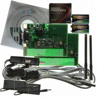
2 DR-TRC103-868EV Boards
2 AA Battery Packs
2 868 MHz Dipole Antennas
4 AA Batteries
ON
TX/RX Mode Range Test Select
Range LED
Related parts for DR-TRC103-915-DK
Image
Part Number
Description
Manufacturer
Datasheet
Request
R

Part Number:
Description:
RFIC TRANCEIVER DEVELOPMENT KIT
Manufacturer:
RFM
Datasheet:

Part Number:
Description:
ASH RX 115.2 KBPS 433.92 MHZ
Manufacturer:
RFM
Datasheet:

Part Number:
Description:
RFIC TRANCEIVER MULTI-CHANNEL FS
Manufacturer:
RFM
Datasheet:

Part Number:
Description:
ASH TX 115.2 KBPS 433.92 MHZ
Manufacturer:
RFM
Datasheet:
Part Number:
Description:
Filters 1602MHz BW=61MHz
Manufacturer:
RFM
Datasheet:

Part Number:
Description:
RESONATOR, SM3030-6
Manufacturer:
RFM
Datasheet:

Part Number:
Description:
RESONATOR, SM3030-6
Manufacturer:
RFM
Datasheet:

Part Number:
Description:
RESONATOR, SM3030-6
Manufacturer:
RFM
Datasheet:

Part Number:
Description:
RESONATOR, SM5035-4
Manufacturer:
RFM
Datasheet:
Part Number:
Description:
RESONATOR 418MHZ SM5035-4
Manufacturer:
RFM
Datasheet:
Part Number:
Description:
WiFi / 802.11 Modules 2.4 and 5.8GHz + BT
Manufacturer:
RFM
Datasheet:

Part Number:
Description:
10-Terminal Ceramic Surface-Mount Case 7 x 5 mm Nominal Footprint
Manufacturer:
RFM [RF Monolithics, Inc]
Datasheet:
Part Number:
Description:
QUAD-BAND GSM850/GSM/DCS/PCS POWER AMP MODULE
Manufacturer:
RFM [RF Monolithics, Inc]
Datasheet:
Part Number:
Description:
402 to 405 MHz Medical Band Front-end Filter
Manufacturer:
RFM [RF Monolithics, Inc]
Datasheet: