STEVAL-TDR011V1 STMicroelectronics, STEVAL-TDR011V1 Datasheet
STEVAL-TDR011V1
Specifications of STEVAL-TDR011V1


Related parts for STEVAL-TDR011V1


STEVAL-TDR011V1 Summary of contents
Page 1
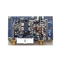
... RF power amplifier with LPF based on the PD85006L-E and STAP85050 RF power transistors Introduction This user manual briefly describes the function and use of the STEVAL-TDR011V1 demonstration board. The board is a two-stage power amplifier which includes an output LPF (low-pass filter) for harmonics rejection. It also features power detection and a temperature sensor. ...
Page 2
... Schematic diagram 1 Schematic diagram The schematic diagram in a) low pass band filter b) power detector c) thermal temperature sensor d) voltage regulator Figure 2. STEVAL-TDR011V1 demonstration board schematic GND 2 INHIBIT 3 2/7 Figure 2 shows the following stages: 14 GND INHIBIT VP2 8 VP1 V( VGS1 1 VGS0 Doc ID 16978 Rev 1 ...
Page 3
... Multimeter 2.2 Connector pin-out Figure 3. Pin-out scheme 2.3 Testing To ensure the correct functioning of the STEVAL-TDR011V1, perform the following procedure: a) Connect a power supply with a high current capability (about 10 A) and set 13 the drain. b) The board features a voltage regulator (VR) to supply temperature sensor (TS) ...
Page 4
Testing procedure The INHIBIT is not internally pulled up, and cannot be left floating. Disable the device when connected to GND positive voltage less than 0. Select the bias gate mode by configuring the wires ...
Page 5
UM0890 Figure 6. Bias mode selection - same Vgg bias to both amplifier stages Figure 7, the two wires must be open in order to apply two independent Vgg biases on In each stage of the amplifier. Figure 7. Bias ...
Page 6
Revision history 3 Revision history Table 1. Document revision history Date 18-Jan-2010 6/7 Revision 1 Initial release. Doc ID 16978 Rev 1 UM0890 Changes ...
Page 7
... UM0890 Information in this document is provided solely in connection with ST products. STMicroelectronics NV and its subsidiaries (“ST”) reserve the right to make changes, corrections, modifications or improvements, to this document, and the products and services described herein at any time, without notice. All ST products are sold pursuant to ST’s terms and conditions of sale. ...