SI1000DK Silicon Laboratories Inc, SI1000DK Datasheet - Page 3
SI1000DK
Manufacturer Part Number
SI1000DK
Description
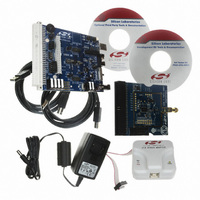
DEVELOPMENT KIT SI101X
Manufacturer
Silicon Laboratories Inc
Type
Development kitr
Specifications of SI1000DK
Mfg Application Notes
SI1000 Code Examples AppNote
Frequency
240MHz ~ 960MHz
Minimum Frequency
434 MHz
Supply Voltage (min)
7 V
Product
RF Development Tools
Maximum Frequency
915 MHz
Output Power
20 dBm
Antenna
SMA
Supply Voltage (max)
15 V
For Use With/related Products
Si100x
Lead Free Status / RoHS Status
Lead free / RoHS Compliant
Lead Free Status / RoHS Status
Lead free / RoHS Compliant, Lead free / RoHS Compliant
Other names
336-1880


4. Connect the USB cable (which will supply power and USB communications).
5. Turn on power: SW5 ON
6. Download the LoadBoard Light code to each. (See "3. Silicon Laboratories IDE Code Download" on page 16).
7. Launch the WDS Chip Configurator application on your PC (Start Silicon Laboratories WDS3)
8. WDS should automatically detect the Si1000 connected via USB. The following screen will appear:
9. Click Radio Control Panel and Select.
10.Configure the radio to transmit a GFSK-modulated PN9 test message:
File location: C:\SiLabs\MCU\Examples\Si100x\EZRadioPRO\WDS_Support\lb_light.hex (Si100x) or
C:\SiLabs\MCU\Examples\Si101x\EZRadioPRO\WDS_Support\lb_light.hex (Si101x)
(Files installed automatically with the Silicon Labs IDE)
Note that the red LED, DS3, blinks when the LoadBoard Light firmware is running.
a. Select the TX state by clicking the TX button,.
b. Set the frequency (903 MHz shown).
c. Set the crystal load capacitance to 10.039 pF.
Rev. 0.1
Si1000/10 QSG
3
Related parts for SI1000DK
Image
Part Number
Description
Manufacturer
Datasheet
Request
R

Part Number:
Description:
QFN 42/I�/915 MHZ, SNAP ENABLED PROGRAMABLE XCVR
Manufacturer:
Silicon Laboratories Inc
Part Number:
Description:
QFN 42/I�/64KB, 4KB RAM, +20 DBM, PROGRAMMABLE XCVR
Manufacturer:
Silicon Laboratories Inc

Part Number:
Description:
IC TXRX MCU + EZRADIOPRO
Manufacturer:
Silicon Laboratories Inc
Datasheet:
Part Number:
Description:
Microcontrollers (MCU) 915MHz SNAP enabled program XCVR
Manufacturer:
Silicon Laboratories Inc
Datasheet:

Part Number:
Description:
BOARD EVALUATION FOR SI1000
Manufacturer:
Silicon Laboratories Inc
Datasheet:

Part Number:
Description:
BOARD EVALUATION FOR SI1000
Manufacturer:
Silicon Laboratories Inc
Datasheet:

Part Number:
Description:
BOARD EVALUATION FOR SI1012
Manufacturer:
Silicon Laboratories Inc
Datasheet:

Part Number:
Description:
BOARD EVALUATION FOR SI1002
Manufacturer:
Silicon Laboratories Inc
Datasheet:

Part Number:
Description:
DEVELOPMENT KIT SI101X
Manufacturer:
Silicon Laboratories Inc
Datasheet:

Part Number:
Description:
BOARD EVALUATION FOR SI1004
Manufacturer:
Silicon Laboratories Inc
Datasheet:

Part Number:
Description:
BOARD EVALUATION FOR SI1004
Manufacturer:
Silicon Laboratories Inc
Datasheet:
Part Number:
Description:
BOARD EVALUATION FOR SI1012
Manufacturer:
Silicon Laboratories Inc
Datasheet:
Part Number:
Description:
BOARD EVALUATION FOR SI1014
Manufacturer:
Silicon Laboratories Inc
Datasheet: