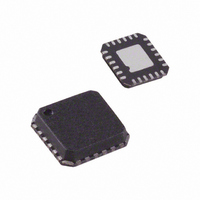
ADL5375-05ACPZ-R7 Analog Devices Inc, ADL5375-05ACPZ-R7 Datasheet - Page 27

ADL5375-05ACPZ-R7
Manufacturer Part Number
ADL5375-05ACPZ-R7
Description
IC MOD QUAD 400MHZ-6GHZ 24LFCSP
Manufacturer
Analog Devices Inc
Datasheet
1.ADL5375-05ACPZ-R7.pdf
(32 pages)
Specifications of ADL5375-05ACPZ-R7
Design Resources
Interfacing ADL5375 to AD9779A Dual-Channel, 1 GSPS High Speed DAC (CN0021) Broadband Low EVM Direct Conversion Transmitter (CN0134)
Function
Modulator
Lo Frequency
400MHz ~ 6GHz
Rf Frequency
400MHz ~ 6GHz
P1db
10.4dBm
Noise Floor
-157.6dBm/Hz
Output Power
1.71dBm
Current - Supply
200mA
Voltage - Supply
4.75 V ~ 5.25 V
Test Frequency
3.5GHz
Package / Case
24-VFQFN, 24-CSP Exposed Pad
Frequency Range
400MHz To 6GHz
Rf Type
Quadrature
Supply Voltage Range
4.75V To 5.25V
Rf Ic Case Style
LFCSP
No. Of Pins
24
Operating Temperature Range
-40°C To +85°C
Frequency Max
6GHz
Lead Free Status / RoHS Status
Lead free / RoHS Compliant
Other names
ADL5375-05ACPZ-R7TR
Available stocks
Company
Part Number
Manufacturer
Quantity
Price
Part Number:
ADL5375-05ACPZ-R7
Manufacturer:
ADI/亚德诺
Quantity:
20 000
EVALUATION BOARD
Populated RoHS-compliant evaluation boards are available
for evaluation of both versions of the ADL5375. The ADL5375
package has an exposed paddle on the underside. This exposed
paddle should be soldered to the board for good thermal and
electrical grounding. The evaluation board is designed without
any components on the underside, so heat can be applied to the
Table 8. Evaluation Board Description and Configuration Options
Component
VPOS, GND Test Points
S1 Switch
R1 to R4, R7 to R12
LOIP SMA, R16, R17
LOIN SMA, R16, R17
49.9Ω
LOIN
LOIP
R15
A
OPEN
R16
S1
R17
0Ω
VPOS
VPOS
Description
Single-ended local oscillator input
Optional SMA for differential LO input
Power Supply and Ground test points for clip leads
DSOP Output Disable Select
Baseband input filtering components
B
1000pF
1000pF
C6
C7
R6
10kΩ
C5
0.1µF
VPOS
COMM
COMM
DSOP
Figure 70. ADL5375 Evaluation Board Schematic
LOIN
LOIP
NC
C3
1000pF
1
2
3
4
5
6
OPEN
QBBN
R5
IBBN
OPEN
OPEN
R11
R8
Rev. A | Page 27 of 32
R3
0Ω
0Ω
R1
EXPOSED PADDLE
ADL5375
OPEN
OPEN
R12
R7
Z1
underside for easy removal and replacement of the ADL5375
should it be necessary.
Both versions of the ADL5375 share the same evaluation board
and schematic. To differentiate the boards from each other,
the silkscreen on the underside of the board has a table that is
marked to indicate which version (-05 or -15) is populated on
the board.
R4
0Ω
R2
0Ω
OPEN
OPEN
R10
R9
QBBP
IBBP
18
17
16
15
14
13
VPS1
COMM
RFOUT
NC
COMM
NC
1000pF
1000pF
Default Condition/Option Settings
Red = 5 V, black = GND
Position A = output enabled
Position B = output disabled
R1 to R4 = 0 Ω (0402)
R7 to R12 = open (0402)
R16 = open, R17 = 0 Ω (0402)
R16 = 0 Ω (0402), R17 = open
C2
C1
GND
0.1µF
C4
RFOUT
VPOS
ADL5375


